Hello and welcome back to the discussion on the TIMERs in compare mode. In the last article we discussed the basics and the theory about using the timer in compare mode. Now its time to write some practical code and run it in real world. The project we are making is a simple time base which is very useful for other project requiring accurate computation of time like a digital clock or a timer that automatically switches devices at time set by user. You can use it for any project after understanding the basics.
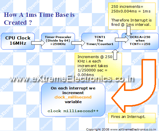
We will have three global variable which will hold the millisecond, second and minutes of time elapsed. These variables are automatically updated by the compare match ISR. Look at the figure below to get an idea how this is implemented.
 |
Fig – Using AVR Timer to generate 1ms Time base. |
|
Complete Code
#include <avr/io.h>
#include <avr/interrupt.h>

#include "lcd.h"

//Global variable for the clock system
volatile unsigned int   clock_millisecond=0;
volatile unsigned char  clock_second=0;

volatile unsigned char  clock_minute=0;

main()
{
   //Initialize the LCD Subsystem
   InitLCD(LS_BLINK);
   //Clear the display
   LCDClear();

   //Set up the timer1 as described in the
   //tutorial

   TCCR1B=(1<<WGM12)|(1<<CS11)|(1<<CS10);
   OCR1A=250;

   //Enable the Output Compare A interrupt
   TIMSK|=(1<<OCIE1A);


   LCDWriteStringXY(0,0,"Time Base Demo");
   LCDWriteStringXY(0,1,"  :   (MM:SS)");

   //Enable interrupts globally

   sei();

   //Continuasly display the time
   while(1)
   {
      LCDWriteIntXY(0,1,clock_minute,2);
      LCDWriteIntXY(3,1,clock_second,2);
      _delay_loop_2(0);
   }

}


//The output compate interrupt handler
//We set up the timer in such a way that
//this ISR is called exactly at 1ms interval
ISR(TIMER1_COMPA_vect)
{
   clock_millisecond++;
   if(clock_millisecond==1000)
   {
      clock_second++;
      clock_millisecond=0;
      if(clock_second==60)
      {
         clock_minute++;
         clock_second=0;
      }
   }
}
Hardware
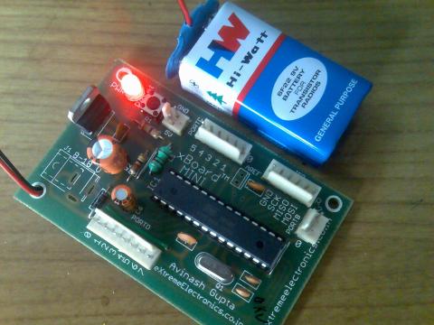
The hardware is ATmega8-16PU running at 16MHz with a LCD Connected to it. I have used xBoard MINI to make the prototype. You can also use your own ATmega8 board. To make a board in your own see this. The output is displayed in a 16×2 character LCD module so please see the LCD interfacing tutorial for information about the connections and use. I recommend you to first setup and test the LCD interfacing because it will help you in many projects. If you have any problems setting it up please post a comment here or use the forum.eXtremeElectronics.co.in
Fig – xBoard MINI can be used to prototype many projects easily! |
|
 |
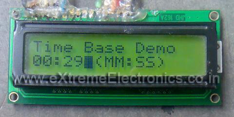
Fig – The output of above program in 16×2 LCD module. |
|
Goodbye for now. Meet you in next tutorials !!! And don’t forget to subscribe to my feed via email to receive latest tutorials direct in your mail box.
Facing problem with your embedded, electronics or robotics project? We are here to help!
Post a help request.


fantastic work! it helped me a lot.
You are Great!
thanks a lot…
Very easy to read and understand.
Thank you very much,has been a great help
Kind regards
James Webster
The best tutorials on the web. 🙂
Very easy to understand.
Kind regards
Rolf
hai to all i m thankful to the people who uploading all these topics ,those are very helpful to understand the concept and very easy to understand…….
Well written and understandable, with images. Took some time to prepair these pages. Excellent work. Thanks
Hey,
one increment take 1/250000 = 0.000004 Sec . How did you say that each increment takes @ 0.000004 Sec? Actually that 250KHz is the clock input for the timer1. Can you please tell me how to calculate?
@ABCD (You don’t even care to enter your real name in lazyness 🙁 )
I can’t explain more than what told above.
Hi,
I am new to microcontrollers. I have started to learn Hardware. Can any one explain me for the following question?
Suppose we are using 120 nanosecond ROMs, which have valid data on the bus 120 ns after the falling edge on the Output Enable line (see Figure 3.4 in the textbook to see how the OE pin is typically connected), and are using the microprocessor discussed in Figure 3.7 with a clock rate of 25 MHz (which means a clock cycle of 40 nanoseconds). How many wait states must the microprocessor insert into each bus cycle that reads from the ROM?
Any good links related to this is also fine
regards,
riya
hey…………..thanks it helped me alot….. nice work…avinash
Good tutorials
Do you have something about DC motor control like the ones used in a tank type vehicle?
NICE WORK AVINASH.
you are really great…Your tutorials are saving lot of time for us..also it is inspiring us to outsource on net projects which we have done…
Alternate method for restoring a dead atmega32.. ya know when you get that device signature = 0x00000 and yikes! from avrdude.
Get a 4mhz (4 pin) crystal.. these are commonly available. The ones that have vcc,gnd and an “out”. Ok.. hook up vcc and gnd then connect crystal out to pin13 of atmega32.
Alternate method for restoring a dead atmega32.. ya know like when you get device signature = 0x00000 and yikes! from avrdude.
Get a 4mhz (4 pin) crystal.. these are commonly available. The ones that have vcc,gnd and an “out”. Ok.. hook up vcc and gnd then connect crystal out to pin13 of atmega32.
AWESOME TUTORIALS
Hello,
I was wondering if you could help me with the following. I want to read data from an accelerometer, which encodes it into PWM form factor. So basically I need to read the PWM output from the sensor and measure the time the signal stays on logic “1”.
I want to do this using the Input Capture Unit from Timer1 (ATMega16). I have tried the following code, but I can’t make the timer trigger on the falling edge. It seems to work fine on rising edge only. Can you tell me what’s wrong with it?
———————————————————
#include
#include
// define global variables
volatile unsigned char t1_overflow = 0;
#define ICP PIND6
//define interrupt routines
ISR(TIMER1_OVF_vect)
{
t1_overflow++;
}
ISR(TIMER1_CAPT_vect)
{
//stop clock
TCCR1B = 0x00;
//clear input capture flag
TIFR&=~(ICF1);
if (ICP) //input pin is high
{
//do stuff here
TCCR1B=0x81;//(1<<CS10) | (1<<ICNC1) ;
}
else //pin is low
{
//do stuff here
//reset timer in desired mode
TCCR1B=0xC1;//(1<<CS10) | (1<<ICNC1)|(1<<ICES1) ;
}
}
int main(void)
{
DDRA=0xFF;
//initialize Timer1
TCCR1A = 0;
TCCR1B=0xC1;//(1<<CS10) | (1<<ICNC1) | (1<<ICES1);
TIMSK|=(1<<TICIE1) | (1<<TOIE1);
TCNT1=0;
ICR1=0;
//enable global interrupts
sei();
//loop infinetly
while ( 1 )
{
};
return 1;
}
Pingback: Timers in Compare Mode – Part I | eXtreme Electronics
Hi,
I have a problem with the program…
Virtually everything in the ATmega8 load, seems to work but it starts to count and after 2 seconds turns off the screen and see a “?” on the right …
The electronic card I built, following the pattern:
“https://extremeelectronics.co.in/avr-projects/avr-project-relay-timer-with-atmega8-avr-mcu/”
I do not know what to do.
thanks
The best tutorials
Thank you very much
excellent work this has helped a lot
Great tutorial! Thanks a lot, this saved me many hours of work!
nice work.
You should make a book out of all these tutorials combined !! Call it say ‘The Alive Projects in Microcontrollers’ !! 🙂
Its really a fantastic tutorial for beginners..It really helped me a lot…Can u tell me how can I set predefined time.So that it can start from 3.40 and not from 0:0
@Khayti,
Please read it once again and go through the code you would get the answer yourself ! 🙂
Sincerely,
follow the good directions of the tutorial I wrote a few lines in an assembler routine to manage the timer 1 ATmega2560 microcontroller. Unfortunately at compile time with the Atmel Studio6 I got so many error messages: “1 operand out of range: 0x0081”. The latter is the address of the register used: for TCCR1B 0x0081, 0x0080 for TCCR1A and so on …
Each instruction OUT I generated the message.
.INCLUDE “m2560def.INC” ;
.DEF tmp = R16
;
.ORG $0000
rjmp avvio
.ORG $0022
rjmp ISR_compara_tc1a
;
ISR_compara_tc1a:
;ISR
reti
avvio:
sbi DDRB,5 ; Imposta la PORTB5 (OC1A) a OUTPUT
ldi tmp,(1 << WGM12) ; Configura il timer 1 per la modalità CTC
out TCCR1B, tmp
ldi tmp,(1 << COM1A0) ; Enable timer 1 Compare Output hannel A
out TCCR1A, tmp
;
ldi tmp, (1 << OCIE1A) ; Abilitazione interrupt di CTC
out TIMSK1, tmp
sei
;
ldi tmp, low(4000) ; carico un valore di prova sul registro OCR1A
out OCR1AL, tmp ; low
ldi tmp, high(4000)
out OCR1AH, tmp ; high
ldi tmp, (1 << CS10) | (0 << CS11); Imposta il prescaler
OUT TCCR1B,tmp
ldi tmp, (1 << OCF1A)
out TIFR1, tmp
MAIN LOOP:
RJMP MAIN_LOOP ;A DO-NOTHING LOOP
With astonishment errors disappear if I set the program to the Timer0. In this case the compilation is correct and this allows me to follow the phases of the program in the simulation Studio6.
Beginner confusion is total and I can not find the error.
I ask for advice and I apologize for the translation made by Google
Can anyone help me in calculating time in atmega 8 which is running parallely with the code .
Like I have 3 input pin pb0 and pb1 and pb2 from which I am checking input. When I get first 1 either from pb0 or pb1 (assuming pb0 ) then I have to start the timer which counts for the time elapsed and simultaneously check the value for other two.When i recieve the the input 1 from pb1 then i have to stop the timer and when i recieve 1 from pb2 i have to keep the timer running. I am a begginer
With the same code above and the F_CPU = 16000000UL, around 20 s increasing every second….
I’m using ATMega32 with AVRDude in Ubuntu 14.04.
Please help me.
I’m just fifteen…..
@Nandu,
Please post your problem here. Also pay attention to the language so that your problem is easily comprehensible!
Thank you for your instant reply.
I’m using Atmega32 with 16MHz crystal..
My programming software is AVRDude(http://www.ladyada.net/learn/avr/avrdude.html) &
Programmer is USBASP.
In 1 second time, around 16 s (pardon me for last comment(20 s) ) is increasing in the lcd.
I meant that you post your problem using that form only! This place for comment is for different purpose, not for problem discussion.
I’m sorry.
I was just asking for a solution to my problem….
Can you help me?
I’m just a beginner….
Hi Avinash,
in your code
” OCR1A=250; ”
Shouldnt it be
OCRA1 = 249;
?