Hello Friends! In this tutorial I will discuss how to practically do a simple communication over RS232 interface. For those who are completely new to this I clarify that the motive is to send and receive data between two device using a standard called RS232. RS232 is serial interface that means that data is transferred BIT by BIT at a time. Since data is transferred BIT by BIT so we need only a single wire two send data and an another one to receive data. One more common wire (called GND) is required between two separate circuit to enable current flow. So a total of three wire are required for communication.
RS232 can be used to communicate between a variety of devices. Like your MCU and a GSM module or a PC. In this tutorial we will demonstrate a link between a PIC18F4520 MCU and a standard PC. On PC we will run a terminal program like RealTerm or Hyperterminal. A terminal program is used to send and receive text data. So any text send by the MCU will be visible on Terminal Screen and Any keypress you make on the PC keyboard will be send over RS232 to your MCU. This configuration is the simplest setup to test and understand RS232 communication. When you have enough knowledge you can replace the Terminal with your own PC end software for sending receiving data.
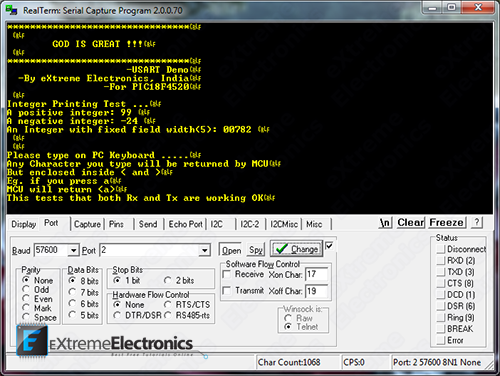
Realterm Terminal Program Displaying the data received from PIC18F |
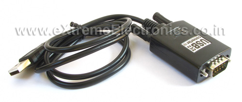
The same functions that we use here to communicate with PC can be used to send/receive data to/from other devices also. But note one thing that modern PCs don’t have a serial port so you need to buy a USB to serial converter. They are available easily at low cost. You can purchase one from our online store.
Fig. USB to Serial Converter |
I recommend you to read and understand the following articles before proceeding.
So basically we have a setup like this.
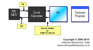 |
Connecting PIC18F4520 with a PC. |
In Serial Communication the line that is used to transmit data is called Tx and the line used to receive data is called Rx. The PIC MCU uses TTL level for logic that is a 1 is a 5v and 0 is 0v but RS232 standard uses different scheme for logic level, so we need a level converter in between. The article that describes how to make a level converter is here RS232 Communication – The Level Conversion.
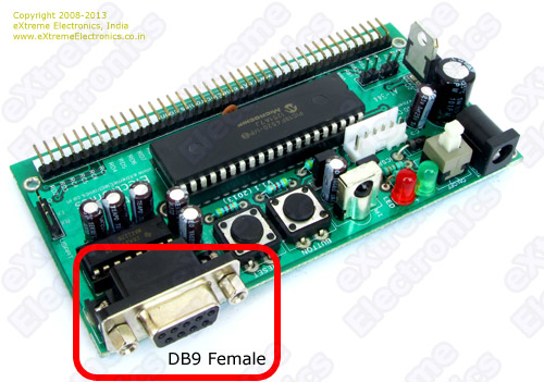
Now the data is ready to be fed to a standard serial port of PC. All good development board has an on board level converter. The following image show the serial port with built in level converter of 40 PIC PIC development board. The MAX232 IC that you can see is industry standard chip for the purpose of level conversion between RS232 and TTL signals.
Fig. DB9 Female on PIC 40 PIN Development Board |
Images below shows how easy it is to connect a USB to Serial Converter to the board.
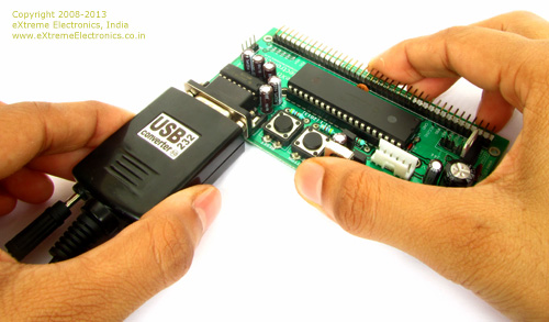 |
Fig. Connecting with Serial Port |
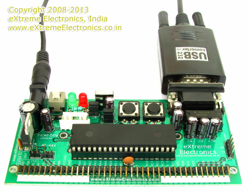 |
Fig. Serial Port Connected |
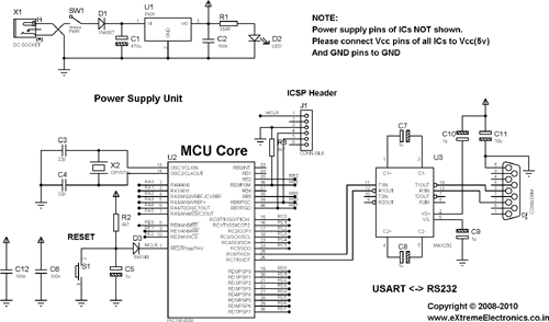
Schematic for Testing Serial Communication with PIC18F4520
PIC18F4520 USART Test Schematic |
The above image show the schematic of circuit you will need to make. Most of the circuit is common for many other application too. The only specific part is the level converter which built around the MAX232 IC. I am explaining in short the parts and their functions.
- Power Supply unit : This part is required in all project. It is built around LM7805 IC. The function of this unit is to provide a regulated 5v supply to other units. I have used a 1N4007 diode to protect this unit from reverse voltage. Even if by mistake you supply wrong polarity the thing wont blow away. For convenience I have also included a LED which will indicate that power supply unit is working OK.
- MCU core: The heart of this unit is PIC18F4520 chip (you may also use PIC18F4550). The ICSP connector is used to download programs via a PIC programmer. RESET switch is used to reset the MCU so its start executing from the beginning of the program. A 20MHz crystal is the source of oscillation. C12 and C6 which are 0.1uF (Marking 104) should be placed as closed to the MCU as possible, they provide extra immunity to noise.
- The level converter: Converts between RS232 to TTL and vice-versa. Explained in more detailed way here -> RS232 Communication – The Level Conversion
Program in HI-TECH C and MPLAB for PIC18F4520
For most of my project I use MPLAB along with HI-TECH C. If you are new to these tools please read the following article. It discuss in details how to obtain, setup and use these tools.
Create a new folder say usart_test in your hard disk. Copy following files to it. You can get those file from the download link at the bottom of this article.
- usart.c
- usart.h
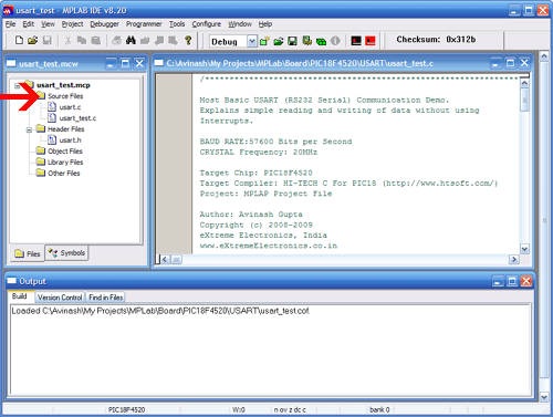
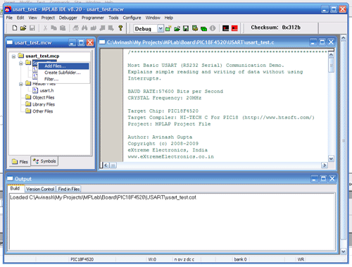
Open MPLAB and create a new project as described here. Now add the "usart.c" file to the "Source Files" section and "usart.h" to the "Header Files" section. To add any file to "Source Files" section right click on "Source Files" in Project window and select "Add Files …" command. Then go the the project folder you just created and select the file.
Right Click On Source File Section |
And Select "Add Files …" option |
After that create a new file using menu option File->New and save it by name usart_test.c . Make sure that "Add File to Project" is selected during saving. Now copy/paste the following program in this new file and save it. To compile and build this project select Rebuild from Project menu. If everything was OK the compilation will succeed and you will get a HEX file ready to burn into you MCU. Please see the following article for more info.
The Hex file can be burnt to the PIC18F4520 MCU using any PIC programmer
/*****************************************************************

Most Basic USART (RS232 Serial) Communication Demo.

Explains simple reading and writing of data without using
Interrupts.

BAUD RATE:57600 Bits per Second
CRYSTAL Frequency: 20MHz

Target Chip: PIC18F4520
Target Compiler: HI-TECH C For PIC18 (http://www.htsoft.com/)
Project: MPLAP Project File

Author: Avinash Gupta
Copyright (c) 2008-2009
eXtreme Electronics, India
www.eXtremeElectronics.co.in

                     NOTICE
                  -------------
NO PART OF THIS WORK CAN BE COPIED, DISTRIBUTED OR PUBLISHED WITHOUT A

WRITTEN PERMISSION FROM EXTREME ELECTRONICS INDIA. THE LIBRARY, NOR ANY PART
OF IT CAN BE USED IN COMMERCIAL APPLICATIONS. IT IS INTENDED TO BE USED FOR
HOBBY, LEARNING AND EDUCATIONAL PURPOSE ONLY. IF YOU WANT TO USE THEM IN
COMMERCIAL APPLICATION PLEASE WRITE TO THE AUTHOR.

*****************************************************************/

#include <htc.h>

#include "usart.h"

//Chip Settings
__CONFIG(1,0x0200);
__CONFIG(2,0X1E1F);
__CONFIG(3,0X8100);
__CONFIG(4,0X00C1);
__CONFIG(5,0XC00F);


void main()
{
   //Initialize the USART
   USARTInit();

   //Write Some line of TEXT
   USARTWriteLine("********************************");
   USARTWriteLine(" ");
   USARTWriteLine("        GOD IS GREAT !!!");
   USARTWriteLine(" ");
   USARTWriteLine("********************************");
   USARTWriteLine("                     -USART Demo");
   USARTWriteLine("  -By eXtreme Electronics, India");
   USARTWriteLine("                 -For PIC18F4520");
   USARTWriteLine(" ");
   USARTWriteLine("Integer Printing Test ...");
   USARTWriteString("A positive integer: ");
   USARTWriteInt(99,255);  //No fixed field lenght i.e. 255

   USARTWriteLine(" ");

   USARTWriteString("A negative integer: ");
   USARTWriteInt(-24,255);  //No fixed field lenght i.e. 255
   USARTWriteLine(" ");

   USARTWriteString("An Integer with fixed field width(5): ");
   USARTWriteInt(782,5);
   USARTWriteLine(" ");

   USARTWriteLine(" ");
   USARTWriteLine(" ");

   USARTWriteLine("Please type on PC Keyboard .....");
   USARTWriteLine("Any Character you type will be returned by MCU");
   USARTWriteLine("But enclosed inside < and >");
   USARTWriteLine("Eg. if you press a");
   USARTWriteLine("MCU will return <a>");
   USARTWriteLine("This tests that both Rx and Tx are working OK");

   //Now Read some input

   while(1)
   {
      char data;

      data=USARTReadByte();   //Wait until a byte is available

      //Now Send the same byte but surrounded by < and >
      //like if user type 'a' we will send <a>

      USARTWriteByte('<');
      USARTWriteByte(data);
      USARTWriteByte('>');

   }
}
Setting Up Realterm
To interact with this demo running on your PIC development board. You need a terminal program. A terminal program is a utility tool running on PC that helps you view text data coming from the serial port and also send data to the port. This is handy for initial development of connected hardwares. It can be downloaded from here.
Start Realterm from its Desktop Icon.
Setup Realterm as follows. Go to the Port Tab and set it as follows.
- Baud: 57600
- Port: Port where you have connected the PIC
- Data bits: 8
- Parity: None
- Stop bits: 1
- Hardware Flow Control: None
Realterm Terminal Program Displaying the data received from PIC18F |
After setting up Realterm, connect the PIC board with COM port and switch it on. You will receive a message on Realterm as shown above.
Once you receive this message, you can be sure that data is easily flowing from the PIC microcontroller to the PC. But now we also need to check if the data is able to reach the MCU from the PC or not.
For this, click on the top large black area of RealTerm and then press any key on the keyboard of your PC. RealTerm will send those data to MCU and if MCU is able to read those data, it will reply back with the same character but enclosed in a <>. That means if you press ‘a‘ on keyboard you will see <a> on the terminal window.
This confirms that MCU is also able to read data from the serial port.
Understanding the USART library for PIC18 Microcontroller
Here I have created a small library to work with USART. This keeps the USART code separate from the application code. The same library can be used in many other project that requires USART communication. The functions available in the library are discussed below.
void USARTInit()
This function initializes the internal USART of the PIC18F4520 microcontroller. This must be called before data can be sent or received. Call it at the program startup.
- Return Value: None
- Parameters: None
void USARTWriteByte(char ch)
Writes a byte of data to the USART.
- Return Value: None
- Parameters: data to be sent.
Example
USARTWriteByte('a');Will send character ‘a’ to the serial port.
void USARTWriteString(const char *str)
This function will send a string of character to the serial port.
- Return Value: None
- Parameters: C Style NULL terminated string.
Example
USARTWriteString("Hello World !");Will send the string "Hello World !" to the serial port. If you have Terminal Program Monitoring that port the message "Hello World !" will be displayed there.
void USARTWriteLine(const char *ln)
Same as the above function but after sending the string it takes the cursor to the beginning of the next line. So next string you send will be printed on new line. If you are working on a Linux based terminal it may now work! In Windows a new line is a CR/LF pair but in Linux it is different.
- Return Value: None
- Parameters: C Style NULL terminated string.
void USARTWriteInt(int val,unsigned char field_length)
This function is used for sending integer values. The second parameter field_length is the lenght of field. Integer can be printed in two ways. One is fixed field length and other is variable field length. In fixed field width you specify the width of field by the parameter field_length. In this case integer will always have this much digits. Leading zeros may be added. Say if you call
USARTWriteInt(99,4)
Then the width of the field will be constant i.e. 4 as passed. So the number will be printed like this
0099
On the other hand variable width integer printing prints as much digit as their are in the original number. So a call like this
USARTWriteInt(99,255); //255 stands for variable width
will print
99
- Return Value: None
- Parameters: val = 16 bit signed integer, field_length= width of field required or 255 for variable width.
unsigned char USARTReadByte()
Wait until a byte is received from USART/Serial Port and return the value read from the USART.
- Return Value: Byte read from USART
- Parameters:None
Example
char data;
data=USARTReadByte();
Now the variable data has the byte received from the USART.
That’s the end of this tutorial. Hope you find it useful. If you have any suggestion do drop in a comment.
Finding the COM Port Number
On windows desktop right click on Computer Icon
 |
Windows Desktop |
Select Properties from the context menu.
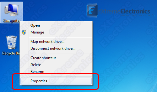 |
Select Properties |
This will open up system properties.
System Properties |
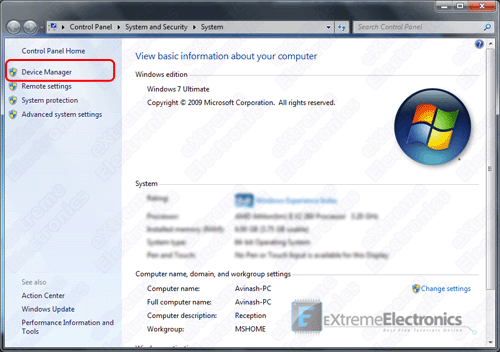
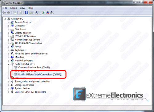
From the left hand side, select Device Manager as shown in the image above. It will open up the Device Manager
Device Manager |
Expand the Ports (COM & LPT) node as shown in the image above. Find the Port Named Prolific USB-to-Serial Comm Port and note the number shown next to it in brackets.
In our case it is COM2 that’s why we have opened Port 2 in RealTerm
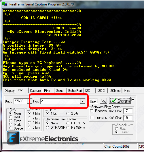 |
Open Port 2 in Real Term |
Important Note !
In order to use the USB to Serial Adapter, it’s driver must be installed correctly ! You can download the drivers from here.
Downloads
- USART Library for PIC18 (HI-TECH C).
- Complete USART Demo Project with HI-TECH C and MPLAB for PIC18F4520
- USART Demo HEX file for PIC18F4520
By
Avinash Gupta
May 11, 2010
Facing problem with your embedded, electronics or robotics project? We are here to help!
Post a help request.



hello,my friend .
This is the first time to this Wedsite.
Your article write very well and easy to learn.
Thank you!
I am a beginner of PIC18F4520 MCU, and I am familiar with Pic16F877A.
I downloaded your code , use the same setup ReakTerm and the same MCU, but I got all (0)zero in the expriment.
CRYSTAL Frequency: 11.0592MHz
void USARTInit()
{
	//Baud Rate = 57600 Bits per Second
	//*** Note: Valid On 20MHz Crystal ONLY ***
	//For other crystal freq calculate new values for SPBRG
	SPBRG=47;

	//TXSTA REG
	TXEN=1;
	BRGH=1;

	//RCSTA
	SPEN=1;
	CREN=1;	//Enable Receiver (RX)

	//BAUDCON
	BRG16=1;

}
The other code is the same with you .
Can you tell me what goes wrong?
@Angel,
Which programmer did you used to program the chip?
Did you write the configuration bits? They are important for setting up the appropriate clock source.
The configuration bits are embedded in souce file and after compilation they are transferred to the HEX file the programmer then MUST read those and program at appropriate locations!
Try changing the crystal to 20Mhz instead of 11.0592
My programmer is “HI-TECH C PRO for the PIC18 MCU Family V9.63PL3”
And “MPLAB IDE v8.10”.
ha, I got it just now.
I forgot the configuration bits.
Now it goes well.
Thank you very much.
Can I ask which country are you from? I am from China.
@Avinash,
I met another problem ,I am sorry!
I changed the baud rate to 9600 by set:
SPBRG=0x1F;
SPBRGH=0x01;
BRGH=1;
BRG16=1;
but the MCU didn’t work again.
I changed the baud rate back to 57600 again, it works.
why? I cannot anderstand.
@Angel.lee
I am from India
Pingback: Introduction to PIC18's Timers - PIC Microcontroller Tutorial | eXtreme Electronics
When I compiled the above code for “PIC16F877a” , the following errors are coming,
Licensed for evaluation purposes only.
This licence will expire on Thu, 29 Jul 2010.
HI-TECH C Compiler for PIC10/12/16 MCUs (PRO Mode) V9.70
Copyright (C) 2009 Microchip Technology Inc.
Error [1346] ; 0. can’t find 0x5 words for psect “config” in segment “CONFIG” (largest unused contiguous range 0x1)
Error [500] ; 0. undefined symbols:
_USARTReadByte(pwnw.obj) _USARTWriteInt(pwnw.obj) _USARTInit(pwnw.obj) _USARTWriteByte(pwnw.obj) _USARTWriteString(pwnw.obj) _USARTWriteLine(pwnw.obj)
********** Build failed! **********
Can u pls help me.
@Thilini,
NO I cannot help as you don’t know how to read!
Can’t you read the the program is ment for a PIC18 arch ??? So why compiling for PIC16 arch ???
Pingback: Look4tech.com » RS232 Communication using PIC18F4520’s USART – PIC Microcontroller Tutorial
Pingback: Interfacing RFID Reader with AVR MCUs - AVR Tutorial | eXtreme Electronics
what changes have to be made for 16f877?
@Saif,
PIC16 and PIC18 are different arc! You have to change compiler and other things.
Better change to PIC18 arch as they are high end & perfect for scalable design where cost isn’t any matter.
Pingback: Introduction to PIC Interrupts and their Handling in C | eXtreme Electronics
aoa! nice article! could we use the same connection of pic to communicate to a mobile phone(gsm modem) which supports serial interface with rs232?in that case how would we check the data that is transmitted or received?what would be the format?
Hello
Great Tutorial !
One question though, if i have a lot of other activities like turning on LEDS and scanning buttons and i am doing this in the main loop where i am also using USARTReadbyte().
Can i loose some messages then ?
As i understand it i must poll the USARTReadbyte() with a high frequency or am i wrong ?
Best Regards
Johan Nilsson
@Johan,
Good question. If we were doing something else while a byte arrived at USART then it will buffer it, but if we were still busy and another byte come in the first one will be lost. To over come this problem we need to write an ISR to handle USART events. As soon as data arrives USART jumps to this ISR which buffers the data in a FIFO queue. This FIFO may have a length of say 64 or 128 byte (depending upon how much RAM you can dedicate to this purpose). Latter application main polling loop when comes to the point where it checks how much data is on queue. It retrieve and process each of them.
This tutorial was a basic intro to PIC USART so I didn’t used Interrupts and FIFO buffers.
@ avinash
does ur library support ISRs??
@Dost Muhammad Sherazi,
Ask it like this
“Does your library utilizes ISR to buffer data ?”
Because
“does ur library support ISRs??”
Means something else.
yes
Does your library utilizes ISR to buffer data ?
Need some help regarding PIC18f97j60
I am new to these PIC18 Family and have not programmed these PICs in MPlab before.
and I have to use MPLAB now , and i am having hard time ..
please help me out in implementing ISR based Rx routine. I am using Picdem.net2 board , have to configure usart as (9600 baud,8bits,No parity,1 stop bit )
Hi,
i’m using interrupt for receiving data. It’s working fine. But how to receive a string data using interrupt. I’ve problem with timing, where data received , I stored it at buffer, but the moment I try to store data, I got another coming..and again..and again. I lost some of the data due to this routine. Do you have any idea how to solve string data received using interrupt. If you can give some code example, I’m really appreciated .Thanks
Hi There,
The internet is truly wonderful knowledge sharing such as what you have demonstrated. Thank you for sharing
I am looking to develop an ethernet to multiple RS232(max of 51) project, and plan to use a PIC 32 for the ethernet service, and have slaves of PIC18s’ to ‘handshake’ RS232 comm. I was wondering if you have come accross such a solution before?
Hi, will this uart communication code work with pic18f6527? I further require this microcontroller to drive a Lin transceiver.Any suggestion on writing the code for LIN communication or any forum which gives it?
Hello my friend, I am new with programming PICs. With RENESAS-CPUs I’m very confident. But now my great problem. I have to transmit and receive data per EUSART2 of PIC18F46J50 and this although per INTERRUPT. Receiving data per INT is OK that functioned. Transmitting data per polling is although no problem, everithing is OK. But transmitting data by interrupt will not function. What I’m doing wrong here ??? This is my code:
//These are my actual interrupt handling routines.
#pragma interrupt YourHighPriorityISRCode
void YourHighPriorityISRCode()
{
#if defined(EUSART2_INTERRUPT_RX) // definiert in uart.h
// EUSART2_INTERRUPT-Receive bearbeiten
UART_Rx();
#endif // EUSART2_INTERRUPT_RX
#if defined(EUSART2_INTERRUPT_TX) // definiert in uart.h
// EUSART2_INTERRUPT-Transmit bearbeiten
UART_Tx();
#endif // EUSART2_INTERRUPT_TX
}
void main(void)
{
// I/O states will be held until DSCONL.RELEASE = 0, but we must still initialize
// to what we want before clearing the RELEASE bit.
InitializeSystem(); // calling some init-routines and …
// InitUART(BAUD_19200,
// DATABITS_8,
// STOPPBITS_1, // not used
// PARITY_NONE, // not used
// FALSE);
INTCONbits.GIE = 1; // Interrupting enabled.
while(1) {
// check Rx-data …
UART_CheckRxData();
MAIN_Wait(10, 10); // ~ 10 ms
// execute UART-functions …
// transmit data per Interrupt …
if (uiTest_State == 0) {
uiTest_State = 1;
// length of Tx-data in byte
stUART_Data.uiTxDataLength = 1;
// pointer to Tx-data
stUART_Data.pcTxData = (char*)&cTest_TxData[1];
stUART_Data.boolTxData = TRUE;
// write first char … then go on per interrupt …
Write2USART(cTest_TxData[0]);
}
} // while(1)
}
void Open2USART_Ext( unsigned char config, unsigned int spbrg)
{
TXSTA2 = 0; // Reset USART registers to POR state
RCSTA2 = 0;
if(config&0x01) // Sync or async operation
TXSTA2bits.SYNC = 1;
if(config&0x02) // 8- or 9-bit mode
{
TXSTA2bits.TX9 = 1;
RCSTA2bits.RX9 = 1;
}
if(config&0x04) // Master or Slave (sync only)
TXSTA2bits.CSRC = 1;
if(config&0x08) // Continuous or single reception
RCSTA2bits.CREN = 1;
else
RCSTA2bits.SREN = 1;
if(config&0x10) // Baud rate select (asychronous mode only)
TXSTA2bits.BRGH = 1;
else
TXSTA2bits.BRGH = 0;
if(config&0x20) // Address Detect Enable
RCSTA2bits.ADDEN = 1;
// SENDB(asychronous mode only) – need to be added
if(config&0x40) // Interrupt on receipt
PIE3bits.RC2IE = 1;
else
PIE3bits.RC2IE = 0;
if(config&0x80) // Interrupt on transmission
PIE3bits.TX2IE = 1;
else
PIE3bits.TX2IE = 0;
SPBRG2 = spbrg; // Write baudrate to SPBRG2
SPBRGH2 = spbrg >> 8; // For 16-bit baud rate generation
TXSTA2bits.TXEN2 = 1; // Enable transmitter
RCSTA2bits.SPEN = 1; // Enable receiver
}
void InitUART(unsigned char ucBaud, unsigned char ucData,
unsigned char ucStopp, unsigned char ucParity,
BOOL boolDspMsg)
{
UART_InitData();
stUART_Para.boolActiv = FALSE;
// Open the USART configured as
// 8N1, 2400 baud, in polled mode (f = 4 MHz)
Open2USART_Ext (USART_TX_INT_ON & // Tx-Int ON
USART_RX_INT_ON & // Rx-Int ON
USART_ASYNCH_MODE & // asynchron mode
ucData & // databits
USART_CONT_RX & // continuous reception
USART_BRGH_HIGH, // high speed mode
ucBaud); // baudrate
UART_Wait(10, 10); // ~ 10 ms OK
// SchnittstellenParameter UART0
stUART_Para.ucVal_Baud = ucBaud;
stUART_Para.ucVal_Databits = ucData;
stUART_Para.ucVal_Stoppbits = ucStopp;
stUART_Para.ucVal_Parity = ucParity;
// Enable interrupt priority
RCONbits.IPEN = 1;
// Make receive interrupt low priority : “0”
// Make receive interrupt high priority : “1”
IPR3bits.RC2IP = 1; // EUSART2 Rx : high priority
TXSTA2bits.TXEN = 1;
_asm
NOP
NOP
_endasm
// Make transmit interrupt low priority : “0”
// Make transmit interrupt high priority : “1”
// IPR3bits.TX2IP = 0; // EUSART2 Tx : low priority
IPR3bits.TX2IP = 1; // EUSART2 Tx : high priority
// Enable all low priority interrupts
INTCONbits.GIEL = 1;
}
Sorry, but some function-code is not complete, but I hope that one can understand what I want to do…
The problem is, when I call the UART-Function => Open2USART_Ext() to initialize EUSART2 with “USART_TX_INT_ON” the program does not reach the main-routine after calling => InitializeSystem().
But when I call the UART-Function => Open2USART_Ext() to initialize EUSART2 with “USART_TX_INT_OFF” the program function normally, but only with sending data without interrupt !!!
Can you please help me ???
Thank you for your fast reply !
Many Thanks… Reiner…
Pingback: Cavalcade of Mammals » Blog Archive » Links for June 2011
thanks a lot & god save you
ok, welcome
Hi,
congratulations for this topic.
I am a beginner in pic18f4553 programming.
It doesn’t work because I don’t use the right bit configuration in my opinion.
Can you give me the configurations bits for this support?
THX
Pingback: PIC16F8870 & RS232 RFID READER & Mikro C
I have run the above code but keep getting this error when using
MPLab-IDE. I have selected the correct controller.
CONFIG1 error
any advice please. I have used all the correct code and the correct circuit diagram
Good day , i want to know the correct chip settings for configuring the pic 18F4520 to use the internal oscillator . If possible can you show them in ‘word/text’ not hexadecimal as in the demo program . Thanks .
Pingback: Serial Communication with PIC16F877A??
This tutorial must be the one of the best. Thanks so much!
help me wireless fire alarm to send and receive ( to GSM Module)
hello
I’m mohammed ( student )
please I wanted to help me
I want to build circuit of wirless fire alarm to send and receive (control panel or to gsm module Interfacing)
very thank you
Good day , i want to know the correct chip settings for configuring the pic 18F4520 to use the internal oscillator
Hi,
That’s a great tutorial. Well I dont know much about microcontroller. So I have a very basic question. I like to make a rotating LED display with PIC which will have its main circuit on a board and serial interfacing part on other board. Instead of making it for a default message, I want to make it for any message. So I want to interface it with PC so if I press any letter, it will be shown on my led display.
Now my question is, is it possible to save the letter in MC I am pressing in hyper-terminal and show that letter in led display board after removing the MC from serial interfacing board? Will the data stay in MC if I disconnect it from serial interfacing board?
Please help! Thanks.
@Afrin,
Yes, you can store the data in MCU’s EEPROM. Its a place which stores data without requiring power supply. It retain data for decades.
Hi, great tutorial. I’d followed, or I should say “I copied” your library file into my project. I’m using PIC18LF2525 with 20MHz connected. I configured the oscillator mode as HS also. Yet, it failed. Any help please? I tried with many different baud rate yet no output from MCU.
dear my engineers bros , that is very useful web site for me , i want to learn more & up grade to my self deeply.
thanks
Best regards
Zubair Muhammad
Hi, good day, good website and great samples.
I’m currently facing a problem after it display the transmitted code, whereby the ‘realterminal’ cannot display the character I type. Was wondering, the caused is from the electronics or the serial to USB converter used is not bi-direction?
Lots of appreciation, if you could help out 🙂 Thanks
Hello dear friends.i would write program which to use datasheet.i don’t like use standart functions.it’i very easy.please,help me about datasheet.
for example:People for programming ADC they use standart functions(Adc_Read etc.)but i want that i write program step by step with datasheet.do you agree with me?help me about that. thanks
hello avinash
i am really thankful to u for this useful tutorial i am beginner and i am using dspic 30f4013 mcu.i learnd the uart and i manage to do the timings and setting up of sfrs. but i dont know how to manage the hyperterminal till i read this article i will try to do my assignment and i will let u know the result once again thnakyou for this article
Pingback: La semana en links (17/04/2012) | Automatismos Mar del Plata
Okay if any one could please help with my project,
my limits is that i use PIC C compiler and Proteus design software for the project.
Farmers’ Tank
-Tank need to be filled up everyday at specific time adjustable by farmer
-Tank level % must be displayed on the 1st line of an lcd
-time to fill tank must be displayed on second line time to be logged for up to 40 days downloadable via rs232 port and clearing data after download
-Use LEDs to indicate pump running , tank full, tank empty.
-include a relay and motor to represent pump
–
–
Pingback: uart driver for pic16f877a - Page 3
I need to build Command string to send to serial port (RS232) .iam usic pic 16f1937
Baudrate is 9600
Parity NONE
Stop bit 2
Protocol is:
ENQ
————————->
PC DEVICE
<————————-
ACK, NAK
error
ENQ = reset communication (PASSWORD)
ACK = command acknoweledged
NAK = command not acknoweledged, try again
error = information about error type
———————————————————————————————————————————–
command,question
————————->
PC DEVICE
<————————-
ACK, NAK
answer
command and answer
STX + channel no+ temperature+crc+ ETX + CHK
Please help me.its urgent.iam new to PIC
I have tried to used the same confoguration bits as my friends did but I keep getting unknown symbols in the hyperterminal like “???” instead of “test”. I am rushing for a project right now so I desprately need someone guidence…. The configuration bits is set from the “Tool–>Configuration Bits” caption of MPLAB
the following is my code
#include
void main()
{
//Initialize the USART
USARTInit();
TRISB = 0x00;
//Write Some line of TEXT
USARTWriteLine(“Test”)
while(1)
{
RB7= 1;
}
}
void USARTInit()
{
SPBRG=129;
//TXSTA REG
TXEN=1;
BRGH=1;
//RCSTA
SPEN=1;
CREN=1; //Enable Receiver (RX)
//BAUDCON
BRG16=0;
}
void USARTWriteByte(char ch)
{
//Wait for TXREG Buffer to become available
while(!TXIF);
//Write data
TXREG=ch;
}
void USARTWriteString(const char *str)
{
while((*str)!=”)
{
//Wait for TXREG Buffer to become available
while(!TXIF);
//Write data
TXREG=(*str);
//Next goto char
str++;
}
}
void USARTWriteLine(const char *ln)
{
USARTWriteString(ln);
USARTWriteString(“\r\n”);
}
void USARTWriteInt(int val,unsigned char field_length)
{
if(val5)
while(str[j]==0) j++;
else
j=5-field_length;
for(i=j;i<5;i++)
{
USARTWriteByte('0'+str[i]);
}
}
unsigned char USARTReadByte()
{
while(!RCIF); //Wait for a byte
return RCREG;
}
Thank You. Can Someone help?
Just wanted to let you know that your tutorial is still an eye-opener for people.
Thanks for sharing your knowledge!!!
Thank you for your fully detailed tutorial. I edited the code to make it work on Pic16f1937,and it worked just perfect. Only one issue I have noticed in function USARTWriteInt(). If you pass zero (e.g USARTWriteInt(0,4); ),you get blank space in the serial monitor(hyper terminal). Any number can be displayed in the serial monitor except the zero. I tried to modify the code,but it’s still not working.
Hi,
am new on your website, i’m doing actually a same application but when i run it i get this message on RealTerm “UART receiver framing error”!!
Can you help me please, i don’t know what a framing error mean!
Reagars
Mike
Hi,
I am using PIC18f4520 to be connected to COM port of PC for serial communication. PIC has a regulated MAX 202C output. Wirings are as follows:
RX of PIC to TX of COM
TX of PIC to RX of COM
GND to GND
But I am not able to get the response in Hyperterminal. Is there anything else I am missing here?
I am using software provided by Mikroelectronika.
Thanks
@Kaushik
Ok we can help you.
But first you need a tested and debugged hardware setup. If you are interested we can provide you with the cost.
Its so easy to understand. Very well
Can you tell me how can i check this on proteus
I have a project of end of study, and I need your help,
my project is to provide a test bed for an electronic card,
and I need a program on PIC that should get Donners card knowing that this card issued tensions that I will compare them later to other signals, a CONTAIN my schema “” MAX “,” PIC 16F876 ,
so I have to receive signals from the map and transmit to the Pc .
Hi Avinash,
Awesome UART library, nicely written (simple & straight). I tested it with my PIC18f458, It works like a charm and very useful. Thanks for sharing 🙂
I am getting error on this line
Error [192] F:\selva\PIC\USART\usart.c; 41.1 undefined identifier “BRG16”
Warning [171] F:\selva\PIC\USART\usart_test.c; 34.18 wrong number of preprocessor macro arguments for “__CONFIG” (2 instead of 1)
Warning [171] F:\selva\PIC\USART\usart_test.c; 35.18 wrong number of preprocessor macro arguments for “__CONFIG” (2 instead of 1)
Warning [171] F:\selva\PIC\USART\usart_test.c; 36.18 wrong number of preprocessor macro arguments for “__CONFIG” (2 instead of 1)
Warning [171] F:\selva\PIC\USART\usart_test.c; 37.18 wrong number of preprocessor macro arguments for “__CONFIG” (2 instead of 1)
Warning [171] F:\selva\PIC\USART\usart_test.c; 38.18 wrong number of preprocessor macro arguments for “__CONFIG” (2 instead of 1)
Post in the helpdesk link given at the end of article.