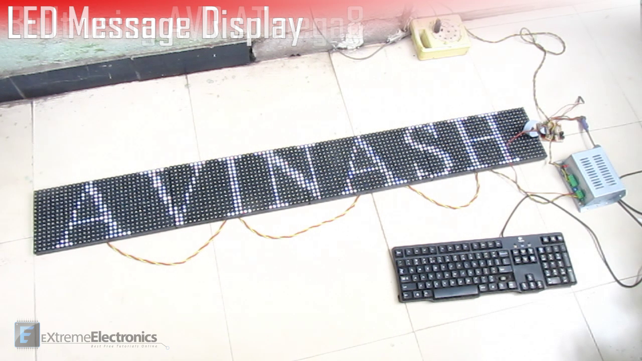
This LED moving message display is four feet in length and six inches in length. Horizontally their are 128 leds and vertically 16. It can show message in English language scrolling from right to left. The system is made using four P10 led display modules and ATmega8 as microcontroller. It has PS/2 keyboard interface that is used to enter message to the board. To enter text, keyboard is connected and Esc key is pressed, this brings the device into text entry mode. After this the whole message is typed using keyboard, at the end of message Enter key is pressed, this saves the message in internal EEPROM of the ATmega8. Now the keyboard can be removed.
Facing problem with your embedded, electronics or robotics project? We are here to help!
Post a help request.


Can u please give me the source code
Jito79@gmail.com
Source code is not free. Cost is Rs. 6000/-
OK i’ll pay, how can I pay?
Do you have Paypal account?
Do you have Paypal account?
Dear Avinash
Can you please give me the source code
hoangtechnology1987@gmail.com
If Source code is not free, how can i pay?
Thank you
Making a LED Message Display using ATmega8 and P10 :-My country Bangladesh, plz give me Source code
dear
i am nasir from bangladesh. we have business led display and led controlor. so many customar have difarent requerment. so i want start business with you. can you give me your whatsup/ wechat number
thank you
Hi Nasir I can help u contact me
already i have mail to you.i am trying p10 with atmega8 for temperature display and for counter.can you help me .please reply .
s nagajothi
Dear Avinash,
Thanks for this usefull information available in your website..
http://digital-wizard.net/avr_projects/p10_led_display_panel_interface
I followed this and interfaced 1 p10 module to my LPC1768 Microcontroller.
Now I am planning to interface 2 p10 modules , one above other, i.e. it becomes 32 rows and 32 columns.
I have few questions:
1. Do I need to have DATA, CLOCK, LATCHseparate, EN, A & B for each p10 module?
2. Since this will be my single unit and in future I will further add P10 modules to expand the columns from 32 to 64 to 96..and so on, keeping the rows same. So, Is there any clock frequency guidelines to be followed ?
Thanks for Your time.
Regards.
Rajesh S
@Rajesh,
You can cascade them.
Hi Avinash,
I will cascade them but do I need separate data clock latch A B lines for each p10 module in parralel? I mean in series we can connect anybno. of p10 one after another; but if two p10 are kept one above another, making 32 rows 32 columns, then separate data clock latch for each module required?
Regards.
Rajesh
Nope, outport of p10 is connected to in port of next p10
I understood what you said. But what if 1 p10 is kept over another p10 such that rows=32 and cols=32. So now I have 1 p10 data clock latch and another p10 above the 1st p10 havong separate data clock latch.
So how to connect data clock latch of each of these p10 modules to microcontroller ?
Regards.
Rajesh
You are talking like a kid, how does it matter where you physically put the displays?
Software must be designed keeping in mind the pixel positions. Connection remains same.
Dear Avinash,
I have started working on ARM stm32F407 based Scrolling p10 led module. For this, I referred your below article :
http://digital-wizard.net/mcu_interfacing/p10_rg_led_display_stm32f030f4
Can You please provide link to download the sample code for this?
Thanks.
Raj S.