Servo Motor Control by Using AVR ATmega32 Microcontroller

Servo motors are a type of electromechanical actuators that do not rotate continuously like DC/AC or stepper motors, rather they used to position and hold some object. They are used where continuous rotation is not required so they are not used to drive wheels (unless a servo is modified). In contrast they are used where something is needed to move to particular position and then stopped and hold there. Most common use is to position the rudder of aircrafts and boats etc. Servos can be used effectively here because the rudder do not need to move full 360 degrees nor they require continuous rotation like a wheel. The servo can be commanded to rotate to a particular angle (say 30) and then hold the rudder there. Servos also employs a feedback mechanism, so it can sense an error in its positioning and correct it. This is called servomechanism. So if the air flow exerts pressure on rudder and deflects it the servo will apply force in opposite direction and try to correct the error. Say if you ask servo to go and lock itself to 30 degrees and then try to rotate it with your hand, the servo will try hard and its best to overcome the force and keep servo locked in its specified angle. Servos are also used […]

Obstacle Avoiding Robot using AVR ATmega32 – Part III

Hello All, Welcome to the third part of the Obstacle Avoiding Robot Tutorial. Till now we have completed the mechanical construction and made the sensor for our robot. I have shown you how to control the motors and read values from sensor in last two parts of the tutorial. In this tutorial we create the master program for our robot. The job of the program is simple, to read values from the sensors, make a decision and command two motors. In this way our robot will roam about the room avoiding obstacles in its path. In our program we define three constants, namely RTHRES,CTHRES and LTHRES in the following way :- //Threshold Values For Sensor Triggering #define RTHRES 195 #define CTHRES 275 #define LTHRES 195 The constant value next to them is the triggering values. You can get this values as described in previous tutorial. Simply run the IR Sensor Test program and bring any obstacle near the sensor at about 15cm (6 inches) and note down these values against respective sensor threshold values. Do same for all three sensor. Now the program knows when the value comes near this threshold value, the sensor has a obstacle in front of it. Note that the value shown above is may not match with the values you obtained, that OK. In our […]

Making “The LCD Expansion Board” for PIC18F4520

In this tutorial I you show you how to make a very useful expansion board for our PIC development board. It will be a Do It Your self (DIY) LCD Expansion board. The expansion board can be plugged into the PIC development board to add 16×2 Alphanumeric LCD Support to it. Since LCDs are required in many projects and experiments it will be a very helpful board. I recommend you to read the LCD Interfacing Tutorial before you proceed. It will give you an Idea how LCD is connected to PIC Microcontrollers. So lets start! Schematic for LCD Expansion Board. Fig.: LCD Module Interface with PIC Microcontroller. The board is very easy to make as the MCU core unit is already done for you. So you need to just care about the LCD part. It consists of the 16×2 LCD Module and A variable resistor (10K) only! Optionally you can add a 47ohm series resistor with the LED backlight of the LCD Module, to enable the backlight. The variable resistor is used to adjust the contrast of the module. If NO text is displayed adjust this pot. All I/O ports and power supply is available at the top of expansion board. Fig.: A blank expansion. As you can see the top row in the board lists all I/O port of […]

Introduction to PIC18’s Timers – PIC Microcontroller Tutorial

Timers are common features of most microcontroller. In simplified terms a timer is just a register whose value keeps increasing (or decreasing) by a constant rate without the help of the CPU. The CPU can read or write this register any time. It reads it find out how much time has elapsed. The Timer register can have the following bit length 8 bit timers – These can count between between 0-255 16 bit timers – These can count between 0-65536 32 bit timers – These can count between 0-4294967296 A timer has a clock source, for example of the clock source of 10KHz is input to a timer then one increment will take 100uS (micro second). This clock source can be obtained from the CPU clock. The CPU clock of popular MCU ranges from 1 MHz to 20Mhz, this can be sometimes too fast. To help us out their is a thing called prescaler in the MCU. The job of prescaler is to divide the CPU clock to obtain a smaller frequency. The PIC Micro that we will use in this example has the following prescaler division factors available. 256 128 64 32 16 8 4 2 1 (Prescaler by-passed) Timers are also called Counters this is because they can be used to count external events. The following example illustrate […]

RS232 Communication using PIC18F4520’s USART – PIC Microcontroller Tutorial

Hello Friends! In this tutorial I will discuss how to practically do a simple communication over RS232 interface. For those who are completely new to this I clarify that the motive is to send and receive data between two device using a standard called RS232. RS232 is serial interface that means that data is transferred BIT by BIT at a time. Since data is transferred BIT by BIT so we need only a single wire two send data and an another one to receive data. One more common wire (called GND) is required between two separate circuit to enable current flow. So a total of three wire are required for communication. RS232 can be used to communicate between a variety of devices. Like your MCU and a GSM module or a PC. In this tutorial we will demonstrate a link between a PIC18F4520 MCU and a standard PC. On PC we will run a terminal program like RealTerm or Hyperterminal. A terminal program is used to send and receive text data. So any text send by the MCU will be visible on Terminal Screen and Any keypress you make on the PC keyboard will be send over RS232 to your MCU. This configuration is the simplest setup to test and understand RS232 communication. When you have enough knowledge you can […]

Obstacle Avoiding Robot using AVR ATmega32 – Part II

Hello and Welcome back to the second part of Obstacle Avoiding Robot Tutorial. In the last part we studied the drive system and the mechanical construction of our robot. In this part we will make the sensor part. The sensors will help our robot detect obstacle in its path. The sensor system is of very basic type of infrared(IR) reflectance sensor. It is made up of an IR Transmitter and an IR receiver. The IR transmitter is an IR LED which emits light in IR spectrum that is invisible to human eye. The IR receiver can detect those rays. A Matching Pair of IR Rx and Tx, The Blue One is Tx (LED). The IR Sensor Element The IR Sensor element is made up of an IR Tx,IR Rx and few resistors. The schematic is given below. We need three such elements mounted in front of the robot to sense obstacles in front of it. IR Reflectance sensor schematic. As you can see the sensor element has two pins for power supply and an Output pin. The output is a variable voltage between 0 and 5v depending on the type and distance of the obstacle. It tends to 5v as some obstacle comes near it. IR Sensor Construction Guidelines. The value of R1 is 150 ohms and R2 is 22K. […]

Multiplexed Seven Segment Display using PIC16F877A and HI-TECH C

#include <htc.h> #define _XTAL_FREQ 20000000UL typedef unsigned char UINT8; typedef signed char INT8; typedef unsigned int UINT16; typedef signed int INT16; //Connection of Seven segment display #define SEVEN_SEGMENT_LAT PORTD #define SEVEN_SEGMENT_TRIS TRISD //MUX Control #define MUX_PORT PORTB #define MUX_START_POS 1 //From which bit on port the select lines start //MUX settings #define MUX_DISP_COUNT 4 //Number of displays //Global Varriable UINT8 DisplayArray[MUX_DISP_COUNT];//Holds ‘data’ for each disp void SevenSegmentWrite(UINT16 n) { /* n=data to dislay example: n=1234 will display 1234 in a 4 segment display Working: This function breaks apart a given integer into separete digits and writes them to the display array i.e. digits[] */ UINT8 i=0; UINT8 j; while(n) { DisplayArray[i]=n%10; i++; if(i==MUX_DISP_COUNT) break; //We don’t have room for more digits n=n/10; } //Fill Unused area with 0 for(j=i;j<MUX_DISP_COUNT;j++) DisplayArray[j]=0; } void WriteSegment(UINT8 num) { switch (num) { case 0: //-GFEDCBA SEVEN_SEGMENT_LAT = 0B01000000; break; case 1: //-GFEDCBA SEVEN_SEGMENT_LAT = 0B01111001; break; case 2: //-GFEDCBA SEVEN_SEGMENT_LAT = 0B00100100; break; case 3: //-GFEDCBA SEVEN_SEGMENT_LAT = 0B00110000; break; case 4: //-GFEDCBA SEVEN_SEGMENT_LAT = 0B00011001; break; case 5: //-GFEDCBA SEVEN_SEGMENT_LAT = 0B00010010; break; case 6: //-GFEDCBA SEVEN_SEGMENT_LAT = 0B00000010; break; case 7: //-GFEDCBA SEVEN_SEGMENT_LAT = 0B01111000; break; case 8: //-GFEDCBA SEVEN_SEGMENT_LAT = 0B00000000; break; case 9: //-GFEDCBA SEVEN_SEGMENT_LAT = 0B00010000; break; } } void Wait() { UINT8 i; for(i=0;i<1;i++) __delay_ms(10); } void main() […]

Obstacle Avoiding Robot using AVR ATmega32 – Part I

Hi and Welcome All, In this tutorial series I will show you how to make a simple obstacle avoiding robot using the xBoard v2.0 microcontroller board. xBoard v2.0 is well suited for developing small intelligent robots as it is compact in size, has four DC motor controller, can be programmed using USB Port and many other features. It is also very easy to learn and use. The xAPI, which is a set of C functions which makes complex programming tasks such as PWM ,LCD, Remote Control etc very easy for beginners. You can buy it from here http://shop.extremeelectronics.co.in/product_info.php?cPath=23&products_id=111 Its design is open so if you don’t want to buy the board you can make it yourself at home by the help of its schematic. The Robo’s Task The task of our robo is simple. To move randomly in an area avoiding obstacles, that’s it ! Though the task is simple, its a complete autonomous robot in itself. It has a brain which reads sensors and makes decisions and command the motors. In the course of making the robot you will learn various basic techniques which will be of great use for your further projects. Our Final Robot will look like this. AVR ATmega32 Based Obstacle Avoiding Robot The following Video Demo Shows the Robo in Action The following Video was […]

Interfacing 12 bit SPI ADC (MCP3204) with AVR Micro

Hello All, Sometimes the Internal ADC is not enough. Like when you need more resolution or high speed. The internal ADC of AVR generally has the following specifications. 15K samples per second 10 bit resolution. If you need more than that you need an external ADC. You may also need external ADCs if you have already used the internal ones. This tutorial will guide you how to install an external ADC with AVR MCU and write a test program to get data from it. A very common external ADC is from Microchip the MCP3204. It has the following configuration. 100K samples per second. (More than 6 times faster than AVRs inbuilt) 12 bit resolution (4 times more detailed) 4 input channels (MCP3208 has 8 channels). SPI Bus Compatible. Basic SPI Tutorial These ADCs are SPI Bus based which is a serial bus. So the number of pins in IC is very low. Total of 4 lines are required to interface it with AVR MCU. MISO (Master In Slave Out) MOSI (Master Out Slave In) SCK (Serial Clock) CS (Chip Select) As you know in synchronous serial communication their is a clock line (SCK in case of SPI) which synchronizes the transfer. Please read the article :- Synchronous Serial Communication Tutorial – The Basics of I2C and SPI. The clock is […]

Sound Generation by AVR Micro – Tutorial I

Many project requires some kind of Audio output. For example a burglar alarm, an automated school bell or simple electronic games or even a robot! In Old days we used some some dedicated Music and Audio Effect chip to do that. At that time ICs such as UM66 were very popular. Now in the days of microcontrollers, a good design is to use least number of external components to get the job done. So if you still use external audio ICs with a MCU based design then your design is inefficient and costly. The smart idea is to get most of the job done in software. In this article we will learn step by step how to produce different kinds of audio effect by just using an AVR MCU and A speaker. After reading this you would be able to provide simple sound output in many AVR based projects. So lets get started! I will start this series with a direct runnable example so that you can burn it into an AVR and see how it sounds! In latter parts I will elaborate how this was achieved. Some techniques that were used to achieve audio generation are. PWM or Pulse width modulation: It is a technique to generate analog voltage levels by a digital device (say a MCU). Generally a […]

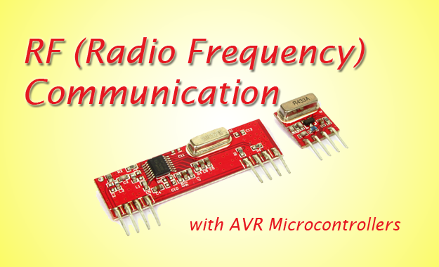
RF Communication Between Microcontrollers – Part III

Welcome to the 3rd part of RF Communication tutorial. In the last two parts I have introduced the basics of RF Communication. RF Communication Between Microcontrollers – Part I : Introduction to RF Communication and Modules. RF Communication Between Microcontrollers – Part II : Algorithm and general description of data transfer. Part III will be covering mostly the practical part, i.e. we will build a complete & working data transfer system. Here you will get circuit and program to implement the solution. The application is very simple in this case, just to transfer a byte of data from Tx station to the Rx station. Once you implement it and get it working you will have enough information and experience to make other RF based projects. I request all users to follows the instruction exactly as given (unless they are smart enough to know what they are doing). The most important thing in this article is timing of the MCU, so Use the exact frequency crystals as used in the designs. Write High Fuse = C9 (HEX Value) and Low Fuse FF (HEX Value) to enable external crystal. Hardware We will have two units. One is Tx (Transmitter) and Other is Rx (Receiver). Both units are based around ATmega16 MCU(you can use ATmega32 also) on external 16MHz crystal. On the Tx […]

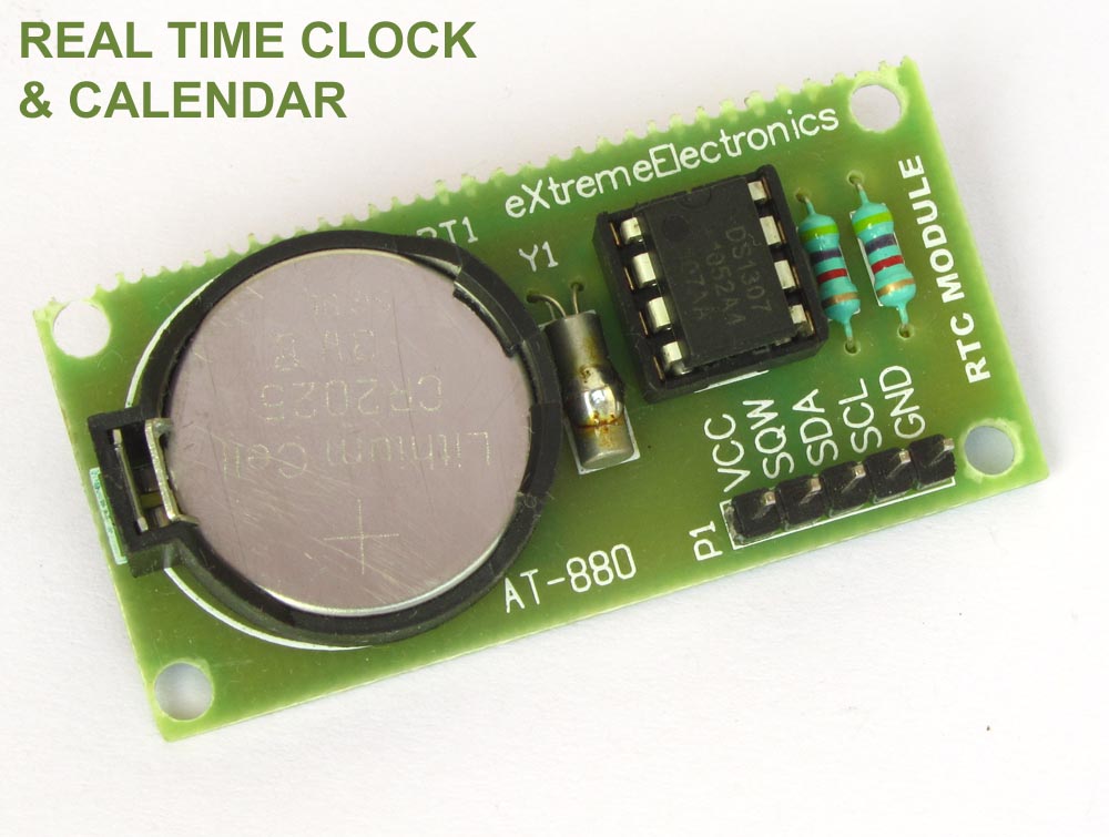
Interfacing DS1307 RTC Chip with AVR Microcontroller

Real Time Clocks, as the name suggests are clock modules. They are available as integrated circuits (ICs) and manages timing like a clock. Some RTC ICs also manages date like a calendar. The main advantage is that they have a system of battery backup which keeps the clock/ca lender running even in case of power failure. A very small current is required for keeping the RTC alive. This in most case is provided by a miniature 3v lithium coin cell. So even if the embedded system with RTC is powered off the RTC module is up and running by the backup cell. This same technique is used in PC timing also. If you have opened your computer case you will notice a small coin cell in the mother board. In this tutorial we will learn to use a very famous RTC IC named DS1307. The DS1307 is described in the datasheet as follows The DS1307 is a low-power clock/calendar with 56 bytes of battery-backed SRAM. The clock/calendar provides seconds, minutes, hours, day, date, month, and year information. The date at the end of the month is automatically adjusted for months with fewer than 31 days, including corrections for leap year. The DS1307 operates as a slave device on the I2C bus. So the aim of the project will be to […]