Multiplexed Seven Segment Displays.

We have discussed the basics of seven segment displays on our tutorial “Using Seven Segment Displays with AVR MCUs”. So you should be familiar with them. In this tutorial we will discuss about multiplexing of seven segment displays.Multiplexing is required when we want to interface 3 or 4 or even more such displays with MCUs since it we go for normal way it will require lots of IO port. So the smart way is multiplexing. Multiplexing achieved by tricking our eyes. Only one display is active at a time but we see all of them active. For multiplexing all the displays are connected in parallel such that if you activate any segment, say ‘a’ the ‘a’ segment of all displays glows up. But the trick is that we can switch on and off the “common” line of the displays under MCU control. So if we wish to light up the ‘a’ segment of display 2 we simply switch on display 2 first by applying proper level at the base of its driving transistor as shown in figure. Fig – Multiplexed Seven Segment Displays. If we like to display the digit say “123” on three displays first we select disp-3 by applying a “low” level at the base of transistor Q1 and output the code of required digit at the data […]

AVR Timers – An Introduction

Timers are standard features of almost every microcontroller. So it is very important to learn their use. Since an AVR microcontroller has very powerful and multifunctional timers, the topic of timer is somewhat “vast”. Moreover there are many different timers on chip. So this section on timers will be multipart. I will be giving basic introduction first. What is a timer ? A timer in simplest term is a register. Timers generally have a resolution of 8 or 16 Bits. So a 8 bit timer is 8Bits wide so capable of holding value withing 0-255. But this register has a magical property ! Its value increases/decreases automatically at a predefined rate (supplied by user). This is the timer clock. And this operation does not need CPU’s intervention. Fig.: Basic Operation Of a Timer. Since Timer works independently of CPU it can be used to measure time accurately. Timer upon certain conditions take some action automatically or inform CPU. One of the basic condition is the situation when timer OVERFLOWS i.e. its counted upto its maximum value (255 for 8 BIT timers) and rolled back to 0. In this situation timer can issue an interrupt and you must write an Interrupt Service Routine (ISR) to handle the event. Fig.: Basic Operation Of a Timer. Using The 8 BIT Timer (TIMER0) The […]

ADC (Analog To Digital Converter) of AVR Microcontroller

Most of the physical quantities around us are continuous. By continuous we mean that the quantity can take any value between two extreme. For example the atmospheric temperature can take any value (within certain range). If an electrical quantity is made to vary directly in proportion to this value (temperature etc) then what we have is Analogue signal. Now we have we have brought a physical quantity into electrical domain. The electrical quantity in most case is voltage.To bring this quantity into digital domain we have to convert this into digital form. For this a ADC or analog to digital converter is needed. Most modern MCU including AVRs has an ADC on chip. An ADC converts an input voltage into a number. An ADC has a resolution. A 10 Bit ADC has a range of 0-1023. (2^10=1024) The ADC also has a Reference voltage(ARef). When input voltage is GND the output is 0 and when input voltage is equal to ARef the output is 1023. So the input range is 0-ARef and digital output is 0-1023. Fig: ADC Theory Inbuilt ADC of AVR Now you know the basics of ADC let us see how we can use the inbuilt ADC of AVR MCU. The ADC is multiplexed with PORTA that means the ADC channels are shared with PORTA. The ADC […]

Using Internal peripherals of AVR MCUs.

Each AVR MCU has several internal peripherals that give powerful abilities to your projects. For example internal ADC can be used to convert analog value (say voltage output of some sensor) to a digital value that you can use. And a USART(Universal Synchronous Asynchronous Receiver Transmitter) can be used to connect your MCU with PC. (Example use – A PC serial mouse or A PC controlled Toy Rocket Launcher). This tutorial gives you overview of the process used to interface with these peripherals. Internal peripherals. Now you know the basics of peripherals, lets see what peripherals are available in ATmega16 MCU. Two 8-bit Timer/Counters with Separate Prescalers and Compare Modes One 16-bit Timer/Counter with Separate Prescaler, Compare Mode, and Capture Mode Real Time Counter with Separate Oscillator Four PWM Channels 8-channel, 10-bit ADC 8 Single-ended Channels 7 Differential Channels in TQFP Package Only 2 Differential Channels with Programmable Gain at 1x, 10x, or 200x Byte-oriented Two-wire Serial Interface Programmable Serial USART Master/Slave SPI Serial Interface Programmable Watchdog Timer with Separate On-chip Oscillator On-chip Analog Comparator Interfacing Technique. Fig: Using internal peripherals of AVR MCUs. A peripheral is connected to MCU by some special registers. The different registers of any peripherals can be logically of two types- 1)Data registers – which usually contains some data, say byte received from USART or […]

Using LCD Module with AVRs

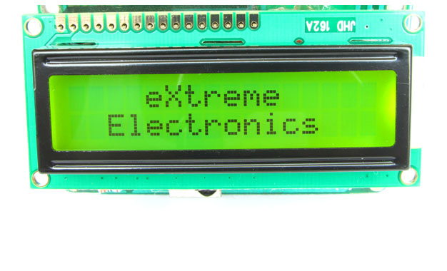
When you start working with LCD modules you will start feeling the real power of MCU and your imaginations will be touching sky you will wonder how many exciting a powerful gadgets you can create and that’s so very easily. LCD Modules can present textual information to user. It’s like a cheap “monitor” that you can hook in all of your gadgets. They come in various types. The most popular one can display 2 lines of 16 characters. These can be easily interfaced to MCU’s, thanks to the API( Functions used to easily access the modules) we provide. LCD interfacing is just fun ! Fig: A 16×2 LCD Module Buy LCD Modules Online In India   PIN Configurations. The lcd modules has 16 PINs for interfacing. The details are given below. LCD Module Pin Configuration 1 VSS (GND Supply) 2 VCC (+5V) 3 VEE (Contrast Adjust) 4 RS 5 R/W 6 E 7 DB0 8 DB1 9 DB2 10 DB3 11 DB4 12 DB5 13 DB6 14 DB7 15 LED + 16 LED –   Connection with ATmega8/ATmega168 etc. The lcd module can be easily connected to the any 28 pin AVR MCU like ATmega8/ATmega168/ATmega328 etc. The diagram below shows the LCD connection with AVR MCUs port pins. Fig: Connection with 28 PIN AVR MCUs Connect the required pins of […]

DC Motor Control using AVR MCUs

Motor gives power to your MCU. Ya power to do physical works, for example move your robot. So it is essential to know how to control a DC motor effectively with a MCU. We can control a DC motor easily with microcontrollers. We can start it, stop it or make it go either in clockwise or anti clock wise direction. We can also control its speed but it will be covered in latter tutorials. A Geared DC Motor. DC Motor A DC motor is electromechanical device that converts electrical energy into mechanical energy that can be used to do many useful works. It can produce mechanical movement like moving the tray of CD/DVD drive in and out (you may like to try it out Go to My Computer, right click the drive icon and click “Eject”). This shows how software controls a motor. DC motors comes in various ratings like 6V and 12V. It has two wires or pins. When connected with power supply the shaft rotates. You can reverse the direction of rotation by reversing the polarity of input. Control with AVR MCUs As the MCUs PORT are not powerful enough to drive DC motors directly so we need some kind of drivers. A very easy and safe is to use popular L293D chips. It is a 16 PIN […]

xBoard™ MINI

If you are new to electronics then it can be a bit of pain for you to get started with MCUs because getting the right hardware tools home made up and running is not easy. But if you want to get started with minimal pain then xBoard™ MINI is for you. This page will give you detail of this state of the art AVR microcontroller learning and development kit from eXtreme Electronics. First Look At xBoard MINI Writing the “Hello World” project with xBoard MINI Programming the Board xBoard MINI can be easily programmed with our easy to use USB AVR Programmer . Check the following tutorials. Introduction to ISP Programming xBoard MINI Pictures Fig – A simple ATmega8 Devboard – The xBoard-MINI   If you wish to buy it, get the xBoard MINI – Simple AVR Development Board from here. It costs only Rs. 450/- and the package includes the board, the AVR MCU (ATmega8), power supply and support CD. Watch the Simple LED blinker the “Hello World” Project of MCU world implemented using the xBoard MINI Meet xBoard MINI’s big brother Fig – A Poweful, ATmega32 based board.

Interfacing Seven Segment Displays

Seven segment displays are very common for electronic product to display numerical output. Many common devices like calculators, watches, electronic weighing scales,ovens etc use them. You must have also seen lifts display the current floor numbers in seven segment displays. So in this article I will show you how to use 7-Segment displays in your own projects. Fundamentals A seven-segment display is so named because it is divided into seven different segments that can be switched on or off. The different combination of these segments switched on produces different English numbers. The display also has a decimal point.   Fig: Seven Segment Display Fig: ‘4’   The figure shows a seven segment display and the names of the various segments. For example if you want to display number 4 then segments that will be ‘on’ are {f,g,b,c} while rest are ‘off’.Basically the seven segments are just LEDs. The one common end of all the leds are connected while the rest are available. Depending on whether anode or cathode of all the leds are common they are of two types. 1) Common anode 2)Common cathode Fig: Common Cathode Type Fig: Common Anode Type PIN Configuration Now you know the basic of these displays, to use them you should know the pin configuration of the commercially available displays. As you must have […]

Input Output Ports of AVR

Digital IO is the most fundamental mode of connecting a MCU to external world. The interface is done using what is called a PORT. A port is the point where internal data from MCU chip comes out or external data goes in. They are present is form of PINs of the IC. Most of the PINs are dedicated to this function and other pins are used for power supply, clock source etc as you have seen in Part III of my tutorials. Ports are named PORTA, PORTB, PORTC, PORTD etc. The pin configuration of ATmege8 mcu is shown below Fig – Mege8 pin configuration   As you can see the pins are labeled PC6,D0,PD1…etc . A port say PORTD is a 8bit register you can set it to any value likePORTD=0xFF; In C language prefix 0x signifies a hexadecimal number here 0xFF means decimal 255 or binary 11111111 which means all the bits in the register is high. A high value on the output port gives +5V and 0 gives ground. You can set the value of PORTD to any required value. This is the basic of digital interface. You can connect LEDs, and switch them on/off from your program. You can connect speaker and produce desired frequency by quickly switching the PORT pin on/off to get sound. But these […]

Home Made AVR Devboard

In this article, I will show you how to make your own AVR development board for ATmega8 microcontroller. What is a development board? In order to learn any MCU like AVR we need a AVR MCU that has all the basic connections like power supply, crystal oscillator, proper reset signal and an ISP connector for uploading a program. All these things are required for any project you will make. A development board is a circuit board that contains all these connections and it has connectors for IO pins of MCU so that they can be connected to any external circuit with ease. So as you see its is like a basic framework. Once you make a good development board and test it, you will have a solid foundation and for your project you can concentrate on the specific requirement of that project. This will also reduce the chance of making errors. Some more complicated development boards have a RS232 level converters(for serial communication) ,motor control chips etc. Now let’s do it! I have described the basic connections required by any AVR MCU in Part III of my AVR tutorial series so I am jumping right to the schematic. Fig – Development board schematic. Things you need are S.No Components Name Value 01 ATmega8 IC1   02 Voltage Regulator IC7805 IC2 […]

Part IV – The “Hello World” project

Now you have the basic hardware tools, its time to setup the software environment.The main software you will need are: AVR Studio – A GUI IDE for AVR(www.atmel.com, http://www.atmel.com/dyn/resources/prod_documents/AVRStudio4.13SP2.exe) WinAVR – a free C compiler for AVRs (http://winavr.sourceforge.net/download.html) PonyProg – Serial Device Programmer (www.lancos.com) After downloading them install them in your computer. It is better to install WinAVR in root of a drive like c:\winavr or d:\winavr. Also please install WinAVR first then AVR Studio, this will let AVR Studio detect the compiler. Now you are ready to write you first microcontroller program !!! In this tutorial, you will learn the basic steps required for any microcontrollers based project. We will write a basic “hello world” project, which is a simple LED blinker in MCU empire to demonstrate these basic steps. Step I Entering and compiling code. Start “AVR Studio” from Start Menu->All programs->Atmel AVR Tools-> AVR Studio 4 You will be presented with a Project wizard as shown below. Fig – AVR Studio Project Wizard Fig – Project Details   Select AVR GCC in Project type then enter a suitable project name say “hello” and select a location in you hard disk. Then click next. Make sure that “Create initial file” and “Create folder” option is checked. Fig – Device Selection   In this dialog box select AVR Simulator […]

Part III – Making Programmer and Target.

Now you know what tools are required for MCU based development. And you are familiar with their uses. Now time to start some real development.To cover these parts you must have some basic knowledge and tools of electroniccircuit fabrication. So now, let us start with the most important tool the programmer. Making a programmer. There are many different types of programmers available on the net. The basic difference is their interface with the PC. Basically, there are three types of programmers. Serial Port based Parallel Port based USB Port based. Of these serial port based and parallel port based programmers are easy to make in minimal cost. However, the parallel port is little bulky as compared to serial port, I prefer serial one. One of the best programmers I have come across is PonyProg(http://www.lancos.com) Serial Device Programmer it is a package of simple and low cost programmer with easy to use GUI software. I have been using it from long time. So here I will teach you to make PonyProg device programmer.   Note As the serials and parallel ports are very old technologies they are fast disappearing from PCs. Most laptops are not having them and even desktops are dropping them. Therefore, its no surprise that your PC does not has serial ports. In this case, you have to […]