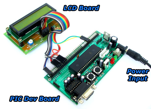
At basic level on microcontroller you can create this interesting project of digital thermometer. It teaches you how to acquire analog data from a sensor and display it on a lcd. We will use a popular MCU PIC16F877A to implement this mini project. The temperature will be read using a LM35 precision sensor. Final result will be shown on a 16×2 alphanumeric lcd module.
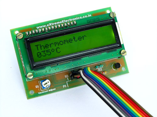 |
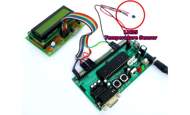
Fig. PIC16F877A Based Thermometer with LCD |
Stuffs Required
| S. No. | Item |
Image | Cost |
| 1 | 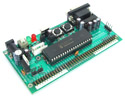 |
Rs. 769 |
|
| 2 | 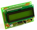 |
Rs. 296 |
|
| 3 | Single PIN Burg Wires Female/Female 20 units |
Rs. 100 |
|
| 4 |  |
Rs. 127 |
|
| 5 | 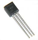 |
Rs. 60 |
|
| Total | Rs. 1,352 |
Connections
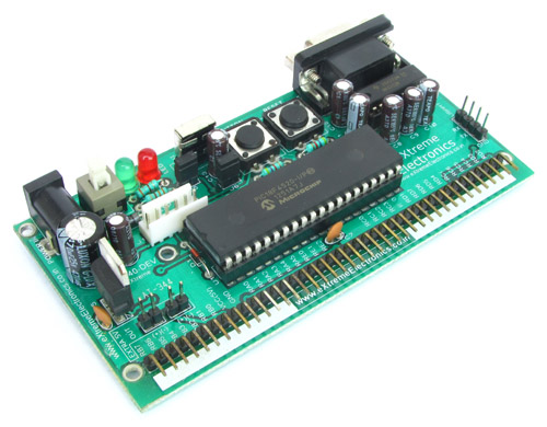
The PIC16F877A development board has the PIC16F877A microcontroller chip and its supporting basic circuitry all in a nice high quality PCB. The development board comes fully assembled and tested, thus makes it ideal for doing experiments for learning by beginners.
40 PIN PIC Development Board |
In the bottom portion of the pic development board you can see a row of male headers. Most of these pins are the microcontrollers general purpose input/output lines and the rest are 5v and GND supply lines. Using these pins you can connect external peripherals (like the LCD board or something else) to do your experiment. The pins are clearly labeled on the PCB surface.
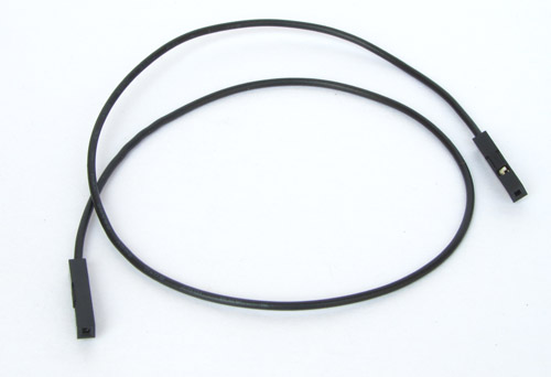
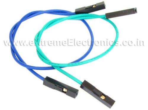
Since other peripheral boards also have male headers for interconnection, you need a female to female burg wires like these to make connections.
Burg Wires |
 |
LCD Board Connection |
Connect LCD Board with the development board using the above mentioned burg wires according to the table given below.
| LCD Board | 40 PIN PIC Dev Board |
| 1 R/W | RB2 |
| 2 RS | RB1 |
| 3 LED PWM | Not Connected |
| 4 VCC | 5v |
| 5 GND | GND |
| 6 DB7 | RD3 |
| 7 DB6 | RD2 |
| 8 DB5 | RD1 |
| 9 DB4 | RD0 |
| 10 E | RD4 |
5v and GND connection points are labeled in the development board as Extra 5v OUT. Please refer to the image below for their positions. 5v and GND are also available in the 40 pin row of male headers. In the image below Yellow wire is 5v and Green wire is GND.
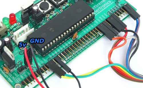 |
Close up of Connection. |
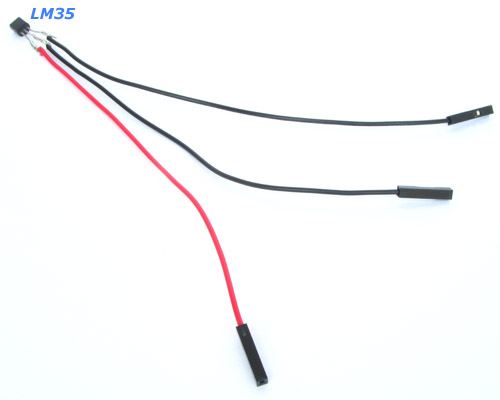
LM35 Connection
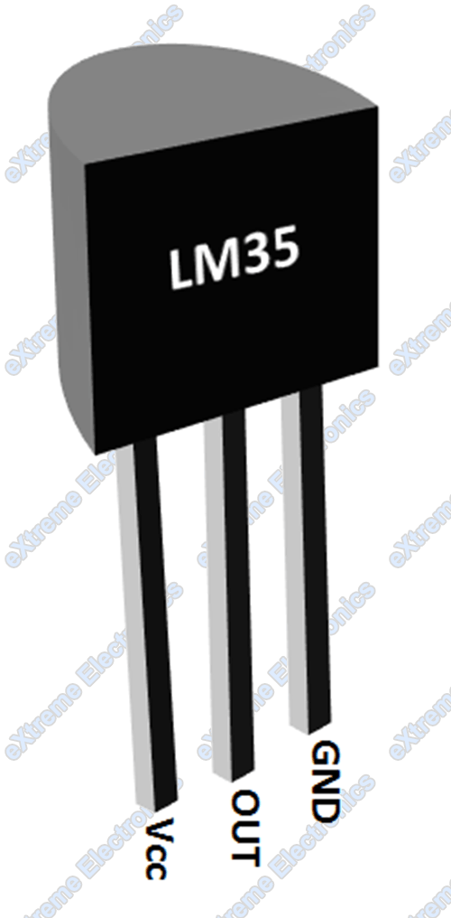 |
LM35 PIN Out |
| LM35 | 40 PIN PIC Dev Board |
| 1 Vcc | Vcc (5v) |
| 2 Out | RA0 |
| 3 GND | GND |
 |
Take a Burg Wire |
 |
Cut it info half |
 |
Remove insulation from one end |
 |
Solder it on LM35 |
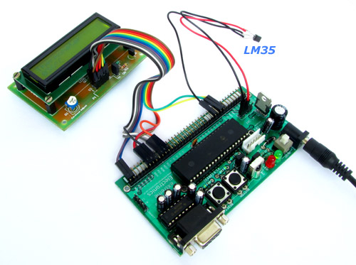 |
Connect it with the development board |
Schematic
Thermometer using PIC16F877A |
Program
/******************************************************************************

 A program to implement a thermometer using a LM35 temperature sensor and a
 16x2 alphanumeric LCD module.

 voltage output from LM35 is measured by using the in built ADC of PIC16f877A
 this is converted to temperature and displayed on the LCD.

 Compiler: Microchip XC8 v1.12 (http://www.microchip.com/xc)
 IDE: Microchip MPLABX

 MCU: PIC16F877A
 Frequency: 20MHz

                                     NOTICE

NO PART OF THIS WORK CAN BE COPIED, DISTRIBUTED OR PUBLISHED WITHOUT A
WRITTEN PERMISSION FROM EXTREME ELECTRONICS INDIA. THE LIBRARY, NOR ANY PART
OF IT CAN BE USED IN COMMERCIAL APPLICATIONS. IT IS INTENDED TO BE USED FOR
HOBBY, LEARNING AND EDUCATIONAL PURPOSE ONLY. IF YOU WANT TO USE THEM IN
COMMERCIAL APPLICATION PLEASE WRITE TO THE AUTHOR.


WRITTEN BY:
AVINASH GUPTA
me@avinashgupta.com

*******************************************************************************/


#include <xc.h>

#include "lcd_hd44780_pic16.h"
#include "adc_pic16.h"
#include "lm35_pic16.h"

// CONFIG
#pragma config FOSC = HS        // Oscillator Selection bits (HS oscillator)
#pragma config WDTE = OFF       // Watchdog Timer Enable bit (WDT disabled)
#pragma config PWRTE = OFF      // Power-up Timer Enable bit (PWRT disabled)
#pragma config BOREN = ON       // Brown-out Reset Enable bit (BOR enabled)
#pragma config LVP = ON         // Low-Voltage (Single-Supply) In-Circuit Serial Programming Enable bit (RB3/PGM pin has PGM function; low-voltage programming enabled)
#pragma config CPD = OFF        // Data EEPROM Memory Code Protection bit (Data EEPROM code protection off)
#pragma config WRT = OFF        // Flash Program Memory Write Enable bits (Write protection off; all program memory may be written to by EECON control)
#pragma config CP = OFF         // Flash Program Memory Code Protection bit (Code protection off)


void main(void)
{
    //Initialize the LCD module
    LCDInit(LS_NONE);

    //Initialize the ADC module
    ADCInit();

    //Clear the LCD
    LCDClear();

    LCDWriteString("Thermometer");

    while(1)
    {
        //Read the temperature using LM35
        float t = LM35ReadTemp();

        //Print it on the LCD
        LCDWriteIntXY(0,1,t,3);

        //Print the degree symbol and C
        LCDWriteString("%0C");

        //Wait 200ms before taking next reading
        __delay_ms(200);
    }

}
How to build from source
To build this project from the source code you need MPLABX IDE and XC8 compiler installed.
- Create a new MPLABX Project
- Name it "thermometer"
- Type: standalone
- Family: Mid Range 8-bit MCUs (PIC12/16/MCP)
- Device: PIC16F877A
- Compiler: XC8
- Add a preprocessor symbol named _XTAL_FREQ=20000000
- Add LCD Library files to project.
- Add ADC library files to project
- Copy the files to your project folder.
- add adc_pic16.c to sources files section.
- add adc_pic16.h to header files section.
- Add LM35 Temperature Sensor library files to project
- Copy the files to your project folder.
- add lm35_pic16.c to sources files section.
- add lm35_pic16.h to header files section.
- Add a new source file thermometer.c this will be the main application file, copy paste the above given source code.
Now its time to build this project. Building is the process of compiling all files in the project and then linking them to build the final executable image. This executable image is in the form of a hex file. The name of this file is <project name>.X.production.hex
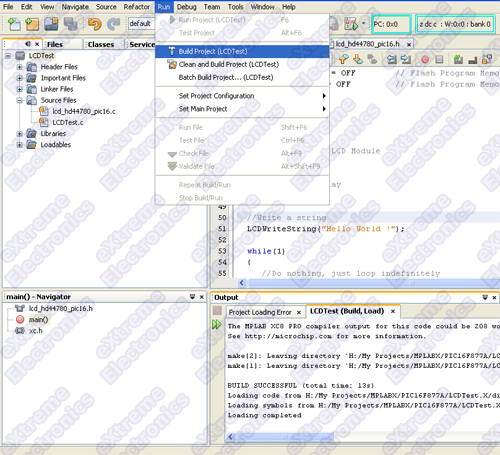
To build the project select Build Project from the Run Menu.
Fig. Building the project |
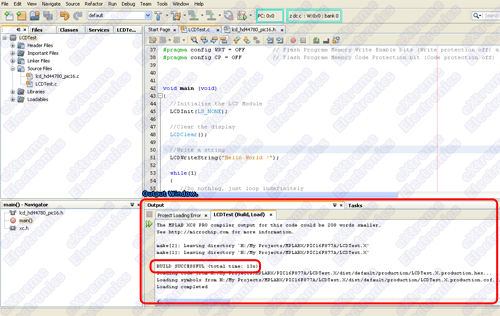
If you have did everything precisely as described in this tutorial your project should build without any problem and you should get a BUILD SUCCESSFUL message in the output window of the MPLAB X IDE.
Fig. Build Success |
The hex file which is actually the executable program in machine language, is generated in the folder "\dist\default\production" which is inside your project folder.
The name of the file should be Thermometer.X.production.hex
Burning the hex file to MCU
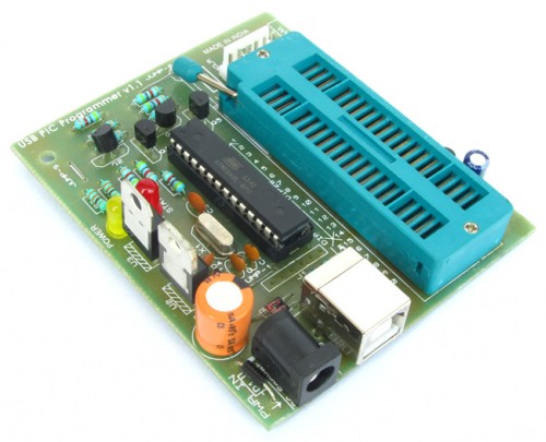
Burning is the process of transferring the data contained in this hex file to appropriate memory locations on the chip so that chip can execute this program. To burn a chip you need a device programmer. A device programmer consists of a hardware and a driving software. You can purchase a device programmer for PIC16F MCUs from our online store. Please note that we ship through out India and to many other countries. International customers can pay safety using Paypal while Indian customer can use Credit Card, Debit Card or Online Banking for purchase.
How to burn the hex file to PIC MCU using this programmer is described in this article.
Fig. USB Port Based PIC Programmer |
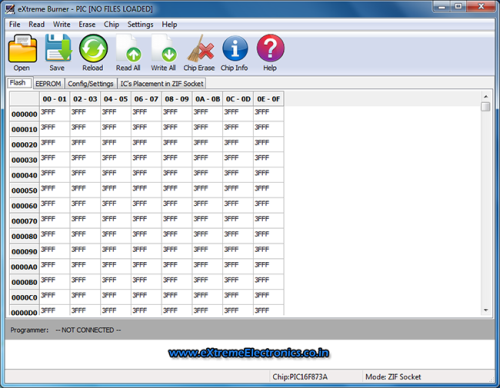 |
Fig. Software Interface |
Downloads
By Avinash Gupta
www.avinashgupta.com
Facing problem with your embedded, electronics or robotics project? We are here to help!
Post a help request.




Dear sir i am a regular customer of your firm,
I am interesting in your product (Making A Thermometer with PIC16F877A)
but i need this kit with function of temperature controlling feature like 3 switches on board example switch 1=Temp + , switch 2=Temp – , and switch 3=select Temperature with out pulse from PIC pin for 1 relay driver etc….. to controlling the Air conditioner compressor
9371012191
9823022191
Hello I am getting this error while downloading hex file with MPLAB X, and PICKIT 3..
Can you help me to understand?
******************
Programming…
program memory
Address: 1 Expected Value: 158a Received Value: 118a
Failed to program device
***********************
@Appos,
Have you programmed anything else with your setup?
Yes.. I had programmed for flashing traffic LEDs
hi
I cant right on the next line of the 16×2 display please help