A line follower robot, or a LFR in short, is a simple autonomous robot that optically tracks a line made on the surface of the floor. That means you have an arbitrary line drawn on the floor and the robot tracks it by moving right along it! The line is sensed using a piece of hardware called a line sensor.
A line sensor can be easily made using a low cost IR Rx/Tx pair. The IR Rx emmits IR radiation and the Rx helps in receiving the waves. See the figure below for working of line sensor.
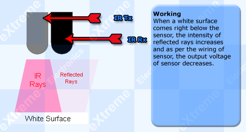 |
Working of Line Sensor |
Schematic for Line Sensor.
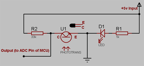 |
Line Sensor Schematic |
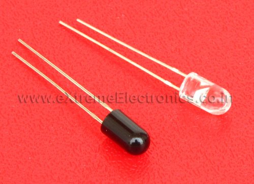 |
Actual IR Rx Tx Pair. |
Line Sensor Array.
Actually a group of such sensor units as described above is required to make a line follower robot. We generally use 3 or 5 such sensor unit to make a line sensor array. The complete steps are described below. You need small piece of veroboard (general purpose PCB).
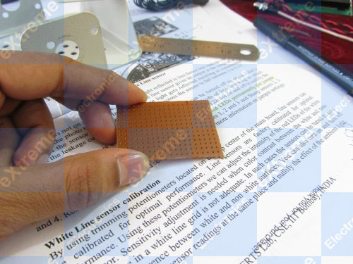 |
Actual IR Rx Tx Pair. |
We will fit the sensor at the castor mount of the metal chassis. So we carefully mark the location we need drilling.
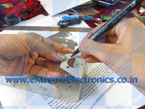 |
Mark drilling location. |
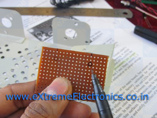 |
Mark the drilling location. |
You can make the hole easily by using a pair of scissor. Just press and rotate.
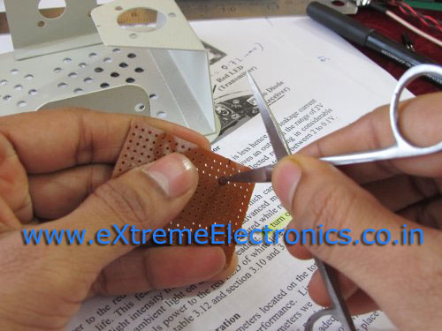 |
Make hole using scissor. |
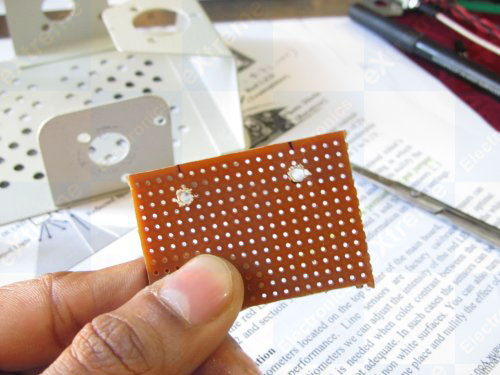 |
Done! |
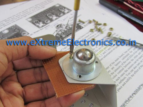 |
Check if it fits. |
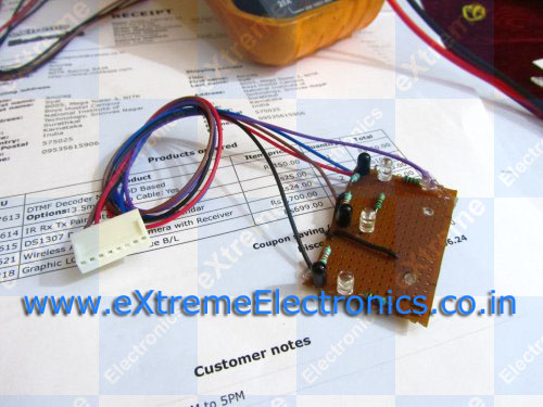 |
Line Sensor Array Complete. |
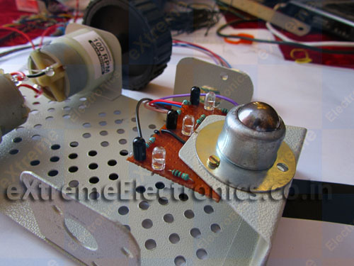 |
Mounted on Chassis. |
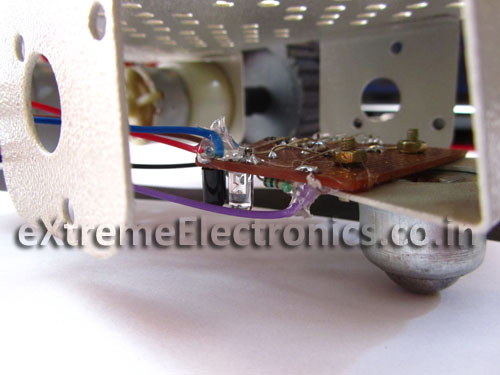 |
Mounted on Chassis. |
Professional Line Sensor Array
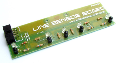 |
Line Sensor Array. |
By Avinash Gupta
Facing problem with your embedded, electronics or robotics project? We are here to help!
Post a help request.


good work
Recently, I purchased LFR from you to demonstrate to my kids. The circuit diagram given in your web site is faint so not readable. Could you kindly send me cleary copy of the circuit diagam of main board? Thank you very much in advance.
@Karunakaran,
It is so because you were too fast in asking. Just click on the image it will enlarge. Today I am feeling pity that even after giving so much info, also I have to teach user “please click here, click there” too !
People quickly find faults in others NOT in their selves. On web site their is only a space for 500pixel wide image so it cannot contain more data than that, you need to click the image to download larger version. Its common sense.
You don’t know how to browse a webpage properly and claiming that the image is faint.
remember even God cannot help those who do not help themselves. It is NOT justified to ask for help in such small situations.
nice.we were also done this but here i expected the real time implementation.please post that sir.
Great Work sir!!!
good work sir!
but can u please tell,how do we select the resistor values or are they fixed?
Gee thanks,i recentry joined your website and i`m enjoying every moment of it.I`m interested in control system which could encompass a radius of about a kilometer in robotics,how can we build such a sateritte and a receiver
Sir if we use more than 3 sensors then what will be overall effect of line follower robot and also please tell that can we make the sensor array for more than 3 sensors the same way as you have described above.
I want to connect 5sensor s to my robot how can i connect .please help me
hello sir, I want to know that here you use phototransistor, why you are not using photodiode?? and I didn’t understood the correct operation of phototransistor here?? Please Explain…
Hello Divyansh, do you know the working of photodiode ? If yes ,then tell me.
Dear Sir, I have bought a line sensor(consisting of 5 Tx-Rx) array from your firm that has been provided with 10 wires for connection using a FRC cable. I just wants to the mechanism that if two pins are there for the supply then how does the rest five pairs feed back their output to the MCU back or they use a common ground.
Hello,
I’m interested in making a simple IR Tx/Rx circuit to detect barriers/blockages/intercepts to the IR ray. Can you help or point me in the right direction.
Thanks
@Subra,
Please see this
https://extremeelectronics.co.in/avr-tutorials/door-entry-detection-for-mcu-based-designs/
Avinash,
Thanks for the reply. Can you suggest how this will be used when Rx cannot be installed on the other side. ie. Tx and Rx must be same side. For example: collision detection. Also do you know if this circuit is sold as a unit, so I can just install. Also, I am looking for a way to program the Rx, so when object is detected, additional action can be taken like sounding an alarm. Thanks in advance
Pingback: How to Use Infrared(IR) Sensors - Tutorials - Into Robotics
This is a great tutorial and this is the reason that I included into an article about IR sensors how to tutorials
sir!
I am designing this sensor board by myself and i have 5pairs of photodetector nd emitter. I am using 1K and 33k resistors but I am confused how to connect the resistors to IR photo detector and emitter, and how to ground them and provide power supply to them.plz help me if you can!
thank you
rajesh
can u give me code for above implementation??
Hello Avinash!
I am Prithul. From your neighbouring country Bangladesh. This tutorial is awesome. I am new to the world of microcontrollers but I’m familiar with Arduino. I just wanna mention you that you can use operational amplifier to read the IR sensors.
-Greetings
Prithul
Hey All, very informative, especially to a newbie like me. I’m also an inventor but my talents seem to lay more in the way of oblong thinking and conceptualization. I create what I like to call PROLUTIONS (product solutions). I often create things that are beyond my technical capabilities. I’m in need of a like-minded counterpart to assist me with a project I’m working on. The product when complete will be cheap to make, address and solve several worthwhile consumer problems and would have mass appeal to the public. It has the potential to revolutionize a popular competition style game that has been played around the world for centuries. I figure I need an ir emitter/sensor and camera (sort of like a wiimote) but need to read multiple areas and be able to relay them to a tablet. Think VIRTUAL KEYBOARD type stuff. Any serious takers that respond I will ask to join me on facebook to validate your person and also ask you sign a nondisclosure agreement before I could provide specifics or discuss compensation and or payment. When I explain the entire project you will be glad you were a part of it.
Please email James, Thanks
Interesting design…..please can u just send the PCB Layout of the main and sensor board.
hello sir i want to know what is pin configuration of 5 ir line sensor array. which pin for ground ,+5v or output.
i want to do a multi colour line sensing robot using ir sensors. can you please help me with that..?
how can we do it using other sensors if any.