Hello and Welcome back to the second part of Obstacle Avoiding Robot Tutorial. In the last part we studied the drive system and the mechanical construction of our robot. In this part we will make the sensor part. The sensors will help our robot detect obstacle in its path. The sensor system is of very basic type of infrared(IR) reflectance sensor. It is made up of an IR Transmitter and an IR receiver. The IR transmitter is an IR LED which emits light in IR spectrum that is invisible to human eye. The IR receiver can detect those rays.
 |
A Matching Pair of IR Rx and Tx, The Blue One is Tx (LED). |
The IR Sensor Element
The IR Sensor element is made up of an IR Tx,IR Rx and few resistors. The schematic is given below. We need three such elements mounted in front of the robot to sense obstacles in front of it.
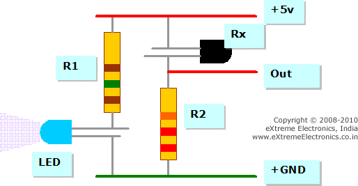 |
IR Reflectance sensor schematic. |
As you can see the sensor element has two pins for power supply and an Output pin. The output is a variable voltage between 0 and 5v depending on the type and distance of the obstacle. It tends to 5v as some obstacle comes near it.
IR Sensor Construction Guidelines.
The value of R1 is 150 ohms and R2 is 22K. The color code is visible in the image above. The values are very critical so please use only the specified values. Also note that the Rx which is BLACK in color (some times transparent glass like also) has its small leg connected to the positive supply, its NOT an error, so connect it exactly that way only.
The IR Rx and Tx should be mounted in such a way that the IR rays from Tx falls on the Obstacle and Return back and hit the Rx. A proper physical layout is shown below.
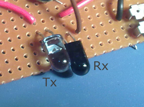 |
IR Rx Tx Mounted On PCB. |
The output of the Sensor element is fed to the Analog To Digital Converter of AVR MCU. The ADC of avr will convert the output to a 10bit digital value which ranges from 0-1024. Thus you can read the ADC to check if the sensor has some obstacle in front of it. Reading ADC is simple in xBoard v2.0 and is documented in details in this tutorial.
Say if we have connected the sensor to ADC0 then the following function will get the status of the sensor.
...
int sensor_value;
sensor_value=ReadADC(0);	//Read Channel number 0
...
For the resistor value as show in the schematic I found out that if no obstacle is in front of the sensor then the value of sensor_value is around 660 and when an Obstacle comes to about 6inches from it, the value goes up to 745. And when the Obstacle comes near than 2.5 inches the value saturates to 1023. It is the MAX value and even if the obstacle comes nearer than that the value remains 1023 only.
Please note that these reading vary with the type of obstacle. Some Object reflects more IR than others. Some reflects very less and then even cannot be detected. The above result was for my palm as the obstacle. Some Object which reflects IR poorly is wood which is painted dark (like a door).
Making the IR Obstacle Sensor
The IR Obstacle sensor for our robot will be made up of three such sensor elements. The sensors will be mounted in front of the robot. One sensor is mounted in the middle and other two on the left and right side respectively.
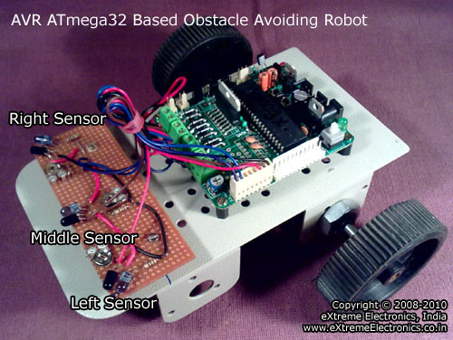 |
Three IR Reflectance Sensor in front of our Robot. |
The whole sensor module is made on a piece of veroboard which you can buy from your local electronic hobby dealer. We begin by cutting the board into a required size. The board can be cut by a small hacksaw blade which can be easily bought from a hardware and tool dealer.
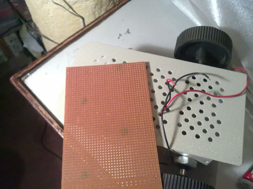 |
A piece of veroboard. |
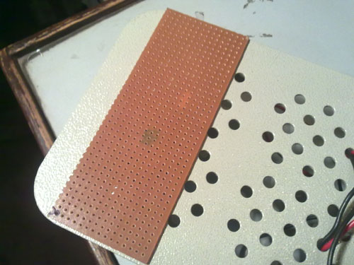 |
A piece of veroboard cut to required size. |
Now we need to drill two holes for mounting. Then we can use screws, nuts and stand-offs to mount the board firmly on the chassis. I have used a powered drill to do the job in seconds but if you don’t have it you can use a hand drill too.
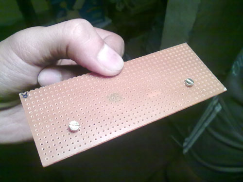 |
Veroboard Drilled and Screws Mounted. |
On the back side, we install spacers on the screws, this will keep some space between the PCB and the chassis.
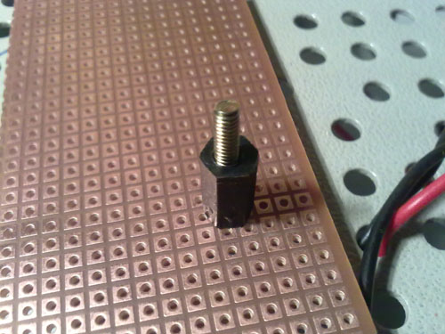 |
The black thing is the spacer. |
Finally the PCB Can be Mounted on the chassis.
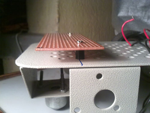 |
Sensor Board Mounted On the Chassis. |
Construct the IR Sensor as shown in the schematic. The Final Board should look like this.
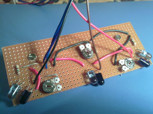 |
The Complete IR Sensor board. |
Please note that I have use presets instead of the fixed 22K resistors. But you should use fixed 22K resistors. The board is connected to the xBoard v2.0 using a standard 8 PIN Relimate Connector. The xBoard v2.0 has a 8 PIN sensor connector where you can connect a variety of sensors. The sensor connector also provides 5v and GND as required by the sensors. The pinout of the xBoard v2.0 sensor connector is shown below.
 |
Sensor Port of xBoard. |
Connect the Right Sensor To ADC0, Center Sensor To ADC1 and Left Sensor to ADC2. Now you are done with the sensor construction part. Lets move on to the testing part.
Testing the IR Sensors.
Below is a small test program that reads and displays the value of all 3 sensors in the LCD Screen. Before attempting the program please go through the LCD Interfacing Routines of xAPI.
/*********************************************************************

                 xBoard(TM) v2.0 Sample Programs

               ------------------------------------


Description :  Simple Utility to View 3 sensor readings on LCD Screen.
            Sensors Must be connected to ADC0,ADC1,ADC2

Author      : Avinash Gupta
Web         : www.eXtremeElectronics.co.in


            Copyright 2008-2010 eXtreme Electronics, India

**********************************************************************/

#include <avr/io.h>

#include <util/delay.h>

#include "lcd.h"

void InitADC()
{
   ADMUX=(1<<REFS0);                                     // For Aref=AVcc;
   ADCSRA=(1<<ADEN)|(1<<ADPS2)|(1<<ADPS1)|(1<<ADPS0);    //Rrescalar div factor =128

}

uint16_t ReadADC(uint8_t ch)
{
   //Select ADC Channel ch must be 0-7
   ch=ch&0b00000111;
   ADMUX&=0b11100000;
   ADMUX|=ch;

   //Start Single conversion
   ADCSRA|=(1<<ADSC);

   //Wait for conversion to complete

   while(!(ADCSRA & (1<<ADIF)));

   //Clear ADIF by writing one to it

   //Note you may be wondering why we have write one to clear it
   //This is standard way of clearing bits in io as said in datasheets.
   //The code writes '1' but it result in setting bit to '0' !!!

   ADCSRA|=(1<<ADIF);

   return(ADC);
}

void Wait()
{
   uint8_t i;
   for(i=0;i<20;i++)
      _delay_loop_2(0);
}


void main()
{
   uint16_t adc_result[3]; //Array

   //Wait for LCD to Startup
   _delay_loop_2(0);

   //Initialize LCD

   LCDInit(LS_BLINK|LS_ULINE);
   LCDClear();

   //Initialize ADC
   InitADC();

   //Welcome and Intro
   LCDWriteString("xBoard Sensor");
   LCDWriteStringXY(0,1,"Test Utility");

   Wait();
   Wait();
   Wait();
   Wait();

   LCDClear();
   LCDWriteString("S#1  S#2  S#3 ");

   while(1)
   {
      adc_result[0]=ReadADC(0);           // Read Analog value from channel-0

     adc_result[1]=ReadADC(1);           // Read Analog value from channel-1
     adc_result[2]=ReadADC(2);           // Read Analog value from channel-2

      LCDWriteIntXY(0,1,adc_result[0],4); //Print the value
     LCDWriteIntXY(5,1,adc_result[1],4); //Print the value

     LCDWriteIntXY(10,1,adc_result[2],4); //Print the value

      Wait();
   }
}
Compile and burn the program to xBoard v2.0 . After That Connect LCD and Sensor Board You made and power up the board. The screen should show the reading of the 3 sensors as shown below.
 |
Screen Shot of xBoard Sensor Test Utility. |
When you bring a Obstacle near one of the sensors the value should go up, bring it nearer and value should approach 1023. Please note down the values of the sensor when NO obstacle is in front of it and when an Obstacle is nearly 6inches (15cm) from it. You will need these value for calibrating the master robot program.
Tips
If you don’t know how to compile and burn programs for xBoard v2.0 then please consult the following documents.
Otherwise I have also provided a HEX file ready to burn to the ATmega32 (or ATmega16 MCU) and run the Utility in no time.
If the LCD Does not show any text please adjust the contrast pot.
If the sensors don’t work as expected then please check the connections. To check if the IR LEDs are working you can use a Handicam (or any other digital camera like you mobile camera). The invisible IR rays are easily visible on Cameras. If the LEDs are NOT emitting IR then check their connections.
Downloads
- xBoard Sensor Test Utility Complete AVR Studio Project for ATmega16 (Version 1.00)
- xBoard Sensor Test Utility Complete AVR Studio Project for ATmega32 (Version 1.00)
- xBoard Sensor Test Utility HEX File ATmega16 (Version 1.00)
- xBoard Sensor Test Utility HEX File ATmega32 (Version 1.00)
Facing problem with your embedded, electronics or robotics project? We are here to help!
Post a help request.


Hello sir,
You are doing a very nice job. Hat’s off to u sir.
Can I expect a tutorial on interfacing of colour lcd with avr microcontroller?
Hi Sir!
It is a good tutorial.But can you help me to make the same robot without using LCD, Just make the robot to avoid obstacle.
Thank you!
When r u gng to put the 3rd tutorial I’am waiting it please put it!
When r u gng to put the 3rd tutorial I’am waiting for it please put it!
sir,i m eagerly waiting for the third tutorial
Pingback: Obstacle Avoiding Robot using AVR ATmega32 – Part III | eXtreme Electronics
@Av
Awesome Tutorial. Serious Time Savers. Thanks again.
good job.
sir if possible could you plz send me the entire project to my mail
@Chaitanya
Ok no problem just pay me US$1000 via Paypal or bank tranfer.
Hi,
From where can I buy those IR LEDs (Tx and Rx)? On ebay I can found only the IR LED Tx (transmitter).
Thank you!
Respected Sir/Madam
I WANT TO WORK ON PROJECT NAMED “OBSTACLE AVOIDING VEHICLE USING ULTRASONIC SENSOR WITH CAMERA MOUNTING”.
GIVE ME UR GUIDANCE THROUGH MAIL.
Thank you.
@Ritesh
Why ???
Are you our customer ?
Helo Sir,
i need your guidance coz i need to make a wall following robot please do help me because i am a beginner and this is a hard task for me
please sir i am waiting for you reply take my email and reply me at madiha285@hotmail.com
that was a good job done.
I also wish you can write the instructions or programs in assembly and basic language.
Respected sir,
I am designing an obstacle detecting bot using IR sensors could you tell me how much sensitivity sensors i need if I want to take a turn on detection of obstacle without getting my bot hit by that obstacle
@CHINMAY
You can not get every thing in theory without doing some practical.If you do practical then you can get your answer by your self.
No one can give answer to your question as your question is incomplete.You don’t mention following thing as expected
1>specification of motor.
2>size of wheel.
3>the nature of surface.
Do it your own so that it will clear to you.
hi .
the schemetic diagram of ir receiver & transmitter iz invisible to us..would u help us out for that.
scemetic diagram is missing or we can no see it kindly help me out
@Ilya,
Please learn to use the browser first. Hit F5 or Ctrl+r to relaod the page again.
thnx 4 ur suggestion.!!
its really nice
but could u please help me to make obstacle detecting robot without using lcd
actually this is little bit of my project
pls,reply me soon sir
thank u
i want ask you some question…i actually new student for electronic..course..and get assignment from my lecture…to create code(coding)….to servo motor move forward and reverse…otherwise if have some obstacle….that infrared sensor distance will detect and mobile robot will go other way….so i don’t no how to build code(assembler code) for this assignment….do you have some idea
thank u to extrem electronics for giving extreme projects.please reply to me how to down load this information
ajitbasha2812@gmail.com
Pingback: Working with a simple IR sensor
I’m going to design a device for visually impared using LPC1248 micro controller.. As i’m from CSE ,i dont know much about sensors and how to make use of sensors with audio feedback.. so pls do help me …
Which type of device you want to make and what will be the function of this device, if you tell me that in detail, then we can certainly help you.
We can suggest you a device which can help visually impaired person to walk .You can make a stick which includes a sensor device called ULTRA SONIC transmitter and receiver. this ultra sonic rx tx along with a microcontroller can be used to detect the obstacles. A buzzer can be connected with this and if it sense any obstacle in its way ,it may starts making a sound .So a visually impaired person can be alert and walk freely.
hey… can u give the backside picture of d sensor board????
it would be a lot of help for beginners like me.
@Sourav,
Please don’t use SMS language, is that ok? Behave like an Educated person! Whats the point in giving multiple question marks?
sorry sir.
i am really sorry for my mistake.
i am unable to assemble the sensor circuit.
can you please help me out?
why you are NOT able to assemble the sensor circuit ? what is the problem?
i am confused whether each sensor circuit out of the three should be in series and then joined to the 5v line or in parellel
and again d output line, should it go from between the resistor and photo diode ?
sensor element schematic is clearly given in the article! each connection is clearly shown. so is their something confusing in the diagram? and spelling of “the” is the NOT d.
sorry . my bad. addiction to sms.
yes sir , my circuit diagram knowledge is kind of weak.
from the diagram i was able to make individual lots of one sensor and one receiver set.
but i am confused how to bring the 3 sets togeder.
and also i have atmega 16 board instead of atmega32. so will the codes work in atmega 16 ?
and also i have atmega16 board instead of atmega32. so will the codes work in atmega16 ?
and if i wish to use four motor drive then what extra codes would i need?
hey i just need to buy a line following and obstacle avoiding Rebot can you provide me with that? I am from Pakistan.Is your service available for me?
Hi Avinash,sorry to bother you. I have a problem. I have to display on the LCD the value given from the ADC when: 1) I have an obstacle between the infrared sensor(emitter) and the Infrared receiver
2)I don’t have an obstacle between the infrared emitter and the infrared receiver
I have to do this for my diploma project. The professor said that somewhere at the middle of these values(when I have an obstacle and when I don’t have an obstacle), will be the Threshold value. Also he said to display the ADC value on the LCD using itoa function. I will send to you the written .c code by me in CodeVision AVR and the circuit build in Proteus. I mention that the value 0 is displyed on the LCD screen with the written code.
Help me please. I really need your help. I wait your answer! Thanks a lot!