If you want a live demo of this, please register from the link given below. (Only in Pune)
REGISTER NOW!
This project can also be implemented using a PIC18F4520 microcontroller. We have schematic and C library available.
A GSM/GPRS Module like SIM300 can be used for any embedded application that requires a long range communication, like a robot in Chennai controlled by a person sitting in New Delhi! Or simply a water pump in a rice field turned on in the morning by a farmer sitting in his house few kilometers away! You have few communication options depending on the application, they may be as follows.
- Simple SMS based communication
- Turn on/off loads using simple SMS commands, so the controlling device is a standard handset. You can use any mobile phone to control the device.
- A intruder alarm/fire alarm that informs about the panic situation to the house owner on his/her mobile via SMS.
- Call based communication
- A smart intruder alarm/fire alarm that calls the police or fire station and plays a pre recorded audio message to inform about the emergency.
- Internet Based Communication (GPRS)
- User can control the end application using any PC/Tablet/Mobile with internet connection. Example: LED Message Displays installed on highways/expressways controlled from a central control room to inform users or traffic conditions ahead.
- A robot controlled over internet. That means the robot can be accessed from any device having internet any where in the world.
- A portable device installed on vehicles that connects to internet using the GPRS Module SIM300 and uploads current position(using Global Position System) to a server. The server stores those location in a database with the ID of vehicle. Then a client(using a PC) can connect with the server using World Wide Web to see the route of the vehicle.
Advantage of using SIM300 Module.
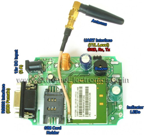
The SIM300 KIT is a fully integrated module with SIM card holder, power supply etc. This module can be easily connected with low cost MCUs like AVR/PIC/8051. The basic communication is over asynchronous serial line. This is the most basic type of serial communication that’s why it is very popular and hardware support is available in most MCUs. The data is transmitted bit by bit in a frame consisting a complete byte. Thus at high level it is viewed as a simple text stream. Their are only two streams one is from MCU to SIM300 and other is from SIM300 to MCU. Commands are sent as simple text. Their are several tutorials that describes how to send and receive strings over the serial line.
If you have never heard of serial communication and never did it in practice then it is highly recommend to go and understand clearly using some thing simpler (experiments given in above links).
Communication with SIM300 Module using AVR UART.
The hardware(inside the AVR MCU Chip) that is used to to serial communication is called the UART, we use this UART to communicate with the SIM300 module (the UART can also be used to communicate with other devices like RFID Readers, GPS Modules, Finger Print Scanner etc.). Since UART is such a common method of communication in embedded world that we have made a clean and easy to use library that we use in all our UART based projects.
Since a byte can arrive to MCU any time from the sender (SIM300), suppose if the MCU is busy doing something else, then what happens? To solve this, we have implemented a interrupt based buffering of incoming data. A buffer is maintained in the RAM of MCU to store all incoming character. Their is a function to inquire about the number of bytes waiting in this queue.
Following are the functions in AVR USART library
void USARTInit(uint16_t ubrrvalue)
Initializes the AVR USART Hardware. The parameter ubrrvalue is required to set desired baud rate for communication. By default SIM300 communicates at 9600 bps. For an AVR MCU running at 16MHz the ubrrvalue comes to be 103.
char UReadData()
Reads a single character from the queue. Returns 0 if no data is available in the queue.
void UWriteData(char data)
Writes a single byte of data to the Tx Line, used by UWriteString() function.
uint8_t UDataAvailable()
Tells you the amount of data available in the FIFO queue.
void UWriteString(char *str)
Writes a complete C style null terminated string to the Tx line.
Example #1:
UWriteString("Hello World !");Example #2:
char name[]="Avinash !";
    UWriteString(name);
void UReadBuffer(void *buff,uint16_t len)
Copies the content of the fifo buffer to the memory pointed by buff, the amount of data to be copied is specified by len parameter. If UART incoming fifo buffer have fewer data than required (as per len parameter) then latter areas will contain zeros.
Example:
char gsm_buffer[128];
    UReadBuffer(gsm_buffer,16);
The above example will read 16 bytes of data (if available) from the incoming fifo buffer to the variable gsm_buffer. Please note that we have allocated gsm_buffer as 128 byte array because latter we may need to read more than 16 bytes. So the same buffer can be used latter to read data up to 128 bytes.
The above function is used generally along with UDataAvailable() function.
while(UDataAvailable()<16)
    {
    	//Do nothing
    }

char gsm_buffer[128];
    UReadBuffer(gsm_buffer,16);
The above code snippet waits until we have 16 bytes of data available in the buffer, then read all of them.
void UFlushBuffer()
Removes all waiting data in the fifo buffer. Generally before sending new command to GSM Module we first clear up the data waiting in the fifo.
The above functions are used to send and receive text stream from the GSM Module SIM300.
SIM300 AT Command Set
Now you know the basics of AVR USART library and how to use it to initialize the USART, send and receive character data, its time for us to move ahead and look what commands are available with SIM300 module and how we issue commands and check the response. SIM300 supports several functions like sending text messages, making phone call etc. Each of the tasks is done using a command, and sim300 has several commands known as the command set.
All SIM300 commands are prefixed with AT+ and are terminated by a Carriage Return (or <CR> in short). The ASCII code of CR is 0x0D (decimal 13). Anything you write to SIM300 will be echoed back from sim300’s tx line. That means if you write a command which is 7 bytes long (including the trailing CR) then immediately you will have same 7 bytes in the MCU’s UART incoming buffer. If you don’t get the echo back then it means something is wrong !
So the first function we develop is SIM300Cmd(const char *cmd) which does the following job :-
(NOTE: All sim300 related function implementations are kept in file sim300.c, and prototypes and constants are kept in sim300.h)
- Writes the command given by parameter cmd.
- Appends CR after the command.
- Waits for the echo, if echo arrives before timeout it returns SIM300_OK(constant defined in sim300.h). If we have waited too long and echo didn’t arrive then it returns SIM300_TIMEOUT.
Implementation of SIM300Cmd()
int8_t SIM300Cmd(const char *cmd)
{
   UWriteString(cmd);   //Send Command
   UWriteData(0x0D); //CR

   uint8_t len=strlen(cmd);

   len++;   //Add 1 for trailing CR added to all commands

   uint16_t i=0;

   //Wait for echo
   while(i<10*len)
   {
      if(UDataAvailable()<len)
      {
         i++;

         _delay_ms(10);

         continue;
      }
      else
      {
         //We got an echo
         //Now check it
         UReadBuffer(sim300_buffer,len);  //Read serial Data

         return SIM300_OK;

      }
   }

   return SIM300_TIMEOUT;

}
Commands are usually followed by a response. The form of the response is like this
<CR><LF><response><CR><LF>
LF is Line Feed whose ASCII Code is 0x0A (10 in decimal)
So after sending a command we need to wait for a response, three things can happen while waiting for a response :
- No response is received after waiting for a long time, reason can be that the SIM300 is not connected properly with the MCU.
- Response is received but not as expected, reason can be faulty serial line or incorrent baud rate setting or MCU is running at some other frequency than expected.
- Correct response is received.
For example, command Get Network Registration is executed like this :-
Command String: "AT+CREG?"
Response:
<CR><LF>+CREG: <n>,<stat><CR><LF>
<CR><LF>OK<CR><LF>
So you can see the correct response is 20 bytes. So after sending command "AT+CREG?" we wait until we have received 20 bytes of data or certain amount of time has elapsed. The second condition is implemented to avoid the risk of hanging up if the sim300 module malfunctions. That means we do not keep waiting forever for response we simply throw error if SIM300 is taking too long to respond (this condition is called timeout)
If correct response is received we analyses variable <stat> to get the current network registration.
depending on current network registration status the value of stat can be
- 0 – not registered, SIM300 is not currently searching a new operator to register to
- 1 registered, home network
- 2 not registered, but SIM300 is currently searching a new operator to register to
- 3 registration denied
- 4 unknown
- 5 registered, roaming
Implementation of SIM300GetNetStat() Function
int8_t SIM300GetNetStat()
{
   //Send Command
   SIM300Cmd("AT+CREG?");

   //Now wait for response
   uint16_t i=0;

   //correct response is 20 byte long
   //So wait until we have got 20 bytes
   //in buffer.
   while(i<10)
   {
      if(UDataAvailable()<20)
      {
         i++;

         _delay_ms(10);

         continue;
      }
      else
      {
         //We got a response that is 20 bytes long
         //Now check it
         UReadBuffer(sim300_buffer,20);   //Read serial Data

         if(sim300_buffer[11]=='1')
            return SIM300_NW_REGISTERED_HOME;
         else if(sim300_buffer[11]=='2')
            return SIM300_NW_SEARCHING;
         else if(sim300_buffer[11]=='5')
            return SIM300_NW_REGISTED_ROAMING;
         else
            return SIM300_NW_ERROR;
      }
   }

   //We waited so long but got no response
   //So tell caller that we timed out

   return SIM300_TIMEOUT;

}
Similarly we have implemented the following functions :-
- int8_t SIM300IsSIMInserted()
In another type of response we don’t exactly know the size of response like we knew for the above command. Example is the Get Service Provider Name command where the provider name’s length cannot be known in advance. It can be Airtel or Reliance or TATA Docomo. To handle that situation we make use of the fact that all response are followed by a CR LF pair. So we simple buffer in all characters until we encounter a CR, that indicates end of response.
To simplify handling of such commands we have made a function called SIM300WaitForResponse(uint16_t timeout)
This function waits for a response from SIM300 module (end of response is indicated by a CR), it returns the size if response received, while the actual response is copied to the global variable sim300_buffer[].
If no response is received before timeout it returns 0. Timeout in millisecond can be specified by the parameter timeout. It does not count the trailing LF or the last <CR><LF>OK<CR><LF>, they remain in the UART fifo queue. So before returning we call UFlushBuffer() to remove those from the queue.
Implementation of function SIM300WaitForResponse(uint16_t timeout)
int8_t SIM300WaitForResponse(uint16_t timeout)
{
   uint8_t i=0;
   uint16_t n=0;

   while(1)
   {
      while (UDataAvailable()==0 && n<timeout){n++; _delay_ms(1);}

      if(n==timeout)
         return 0;
      else
      {
         sim300_buffer[i]=UReadData();

         if(sim300_buffer[i]==0x0D && i!=0)
            return i+1;
         else
            i++;
      }
   }
}
Implementation of function SIM300GetProviderName(char *name)
The function does the following :-
- Flush the USART buffer to get rid of any leftover response from the last command or errors.
- It send the command "AT+CSPN?" using SIM300Cmd("AT+CSPN?"); function call.
- Then it waits for a response using the function SIM300WaitForResponse()
- If we receive a response of non zero length we parse it to extract string describing the service provider name.
- If SIM300WaitForResponse() returns zero that means no valid response is received within specified time out period. In this case we also return SIM300_TIMEOUT.
In the same way we have implemented the following functions :-
- uint8_t SIM300GetProviderName(char *name)
- int8_t SIM300GetIMEI(char *emei)
- int8_t SIM300GetManufacturer(char *man_id)
- int8_t SIM300GetModel(char *model)
uint8_t SIM300GetProviderName(char *name)
{
   UFlushBuffer();

   //Send Command
   SIM300Cmd("AT+CSPN?");

   uint8_t len=SIM300WaitForResponse(1000);

   if(len==0)
      return SIM300_TIMEOUT;

   char *start,*end;
   start=strchr(sim300_buffer,'"');
   start++;
   end=strchr(start,'"');

   *end='\0';

   strcpy(name,start);

   return strlen(name);
}
SIM300 and ATmega32 Hardware Setup
Buy xBoard NOW !
Free shipping across India ! Pay Cash on Delivery ! 15 Days Money Back!
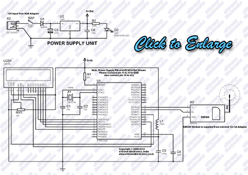
To run the basic demo showing communication with SIM300 using AVR ATmega32 we need the following circuit :-
- ATmega32 Core circuit, including the reset register, ISP header, 16MHz crystal oscillator.
- Power Supply circuit to supply 5v to the ATmega32 and the LCD Module.
- A 16×2 Alphanumeric LCD Module to show programs output.
- SIM300 Module.
Fig. SIM300 and ATmega32 Schematic |
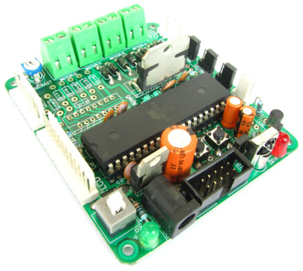
We have made the prototype using xBoard development board because it has ATmega32 core circuit, 5v power supply circuit and the LCD module.
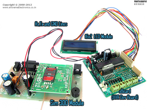 |
Fig. SIM300 and ATmega32 Connection |
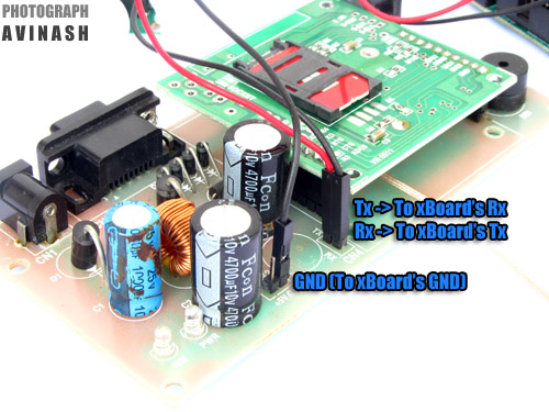 |
Fig. SIM300’s PINs |
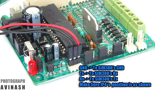 |
Fig. xBoard’s USART PINs |
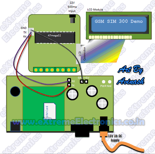 |
Fig. GSM Module connected with ATmega32 |
NOTE
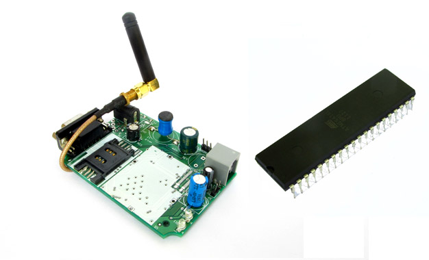
The board shown below is the new version of SIM300 Modem, it can also be used to make this project. New version is much smaller and low cost.
Fig. SIM300 Module New Version |
Demo Source Code for AVR and SIM300 Interface
The demo source code is written in C language and compiled using free avr-gcc compiler using the latest Atmel Studio 6 IDE. The project is split into the following modules.
- LCD Library
- Files lcd.c, lcd.h, myutils.h, custom_char.h
- Job is to control standard 16×2 LCD Module.
- More information on LCD library.
- USART Library
- Files usart.c,usart.h
- Job is to control the USART hardware of AVR MCU. Includes functions to initialize the USART, Send/Receive chars, Send/Receive Strings.
- SIM300 Library
- Files sim300.c, sim300.h
To build the project you need to be have working knowledge of the Atmel Studio 6 IDE. Please refer to the following tutorial.
- Working with latest Atmel Studio 6 IDE.
Steps to configure the AS6 Project
- Create a new AS6 Project with name "Sim300Demo".
- Using solution explorer create a folder named "lib" in current folder.
- Inside the "lib" folder create the following sub folders "lcd", "usart" and "sim300".
- copy followings files to the lcd folder (using Windows File Manager) lcd.c, lcd.h, myutils.h, custom_char.h
- copy followings files to the usart folder (using Windows File Manager) usart.c,usart.h
- copy followings files to the sim300 folder (using Windows File Manager sim300.c, sim300.h
- Add the files lcd.c, lcd.h, myutils.h, custom_char.h to the project using solution explorer.
- Add the filesusart.c,usart.h to the project using solution explorer.
- Add the files sim300.c, sim300.h to the project using solution explorer.
- Define a symbol F_CPU=16000000 using AS6’s
- in the main application file Sim300Demo.c copy paste the following demo program.
- Build the project to get the executable hex file.
- Burn this hex file to the xBoard using USB AVR Programmer.
- If you are using a new ATMega32 MCU from the market set the LOW FUSE as 0xFF and HIGH FUSE are 0xC9.
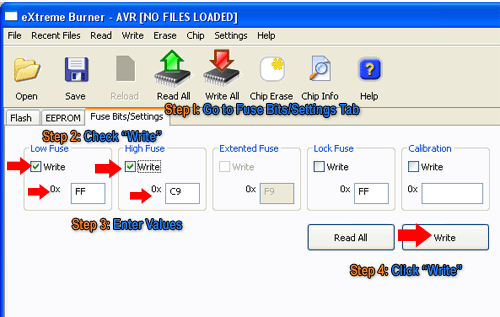 |
Fig.: Setting the Fuse bytes. |
/*
 * Sim300Demo.c
 *
 * Created: 10-07-2012 PM 12:23:08
 *  Author: Avinash
 */


#include <avr/io.h>
#include <util/delay.h>

#include "lib/lcd/lcd.h"
#include "lib/sim300/sim300.h"


void Halt();
int main(void)
{
   //Initialize LCD Module
   LCDInit(LS_NONE);

   //Intro Message
   LCDWriteString("SIM300 Demo !");
   LCDWriteStringXY(0,1,"By Avinash Gupta");

   _delay_ms(1000);

   LCDClear();


   //Initialize SIM300 module
   LCDWriteString("Initializing ...");
   int8_t r= SIM300Init();

   _delay_ms(1000);

   //Check the status of initialization
   switch(r)
   {
      case SIM300_OK:
         LCDWriteStringXY(0,1,"OK !");
         break;
      case SIM300_TIMEOUT:
         LCDWriteStringXY(0,1,"No response");
         Halt();
      case SIM300_INVALID_RESPONSE:
         LCDWriteStringXY(0,1,"Inv response");
         Halt();
      case SIM300_FAIL:
         LCDWriteStringXY(0,1,"Fail");
         Halt();
      default:
         LCDWriteStringXY(0,1,"Unknown Error");
         Halt();
   }

   _delay_ms(1000);

   //IMEI No display
   LCDClear();

   char imei[16];

   r=SIM300GetIMEI(imei);

   if(r==SIM300_TIMEOUT)
   {
      LCDWriteString("Comm Error !");
      Halt();
   }

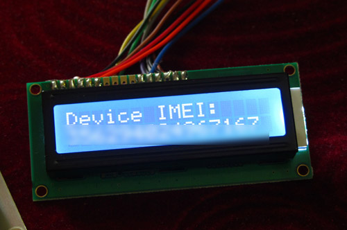
   LCDWriteString("Device IMEI:");
   LCDWriteStringXY(0,1,imei);

   _delay_ms(1000);

   //Manufacturer ID
   LCDClear();

   char man_id[48];

   r=SIM300GetManufacturer(man_id);

   if(r==SIM300_TIMEOUT)
   {
      LCDWriteString("Comm Error !");
      Halt();
   }

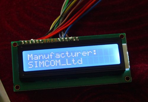
   LCDWriteString("Manufacturer:");
   LCDWriteStringXY(0,1,man_id);

   _delay_ms(1000);

   //Manufacturer ID
   LCDClear();

   char model[48];

   r=SIM300GetModel(model);

   if(r==SIM300_TIMEOUT)
   {
      LCDWriteString("Comm Error !");
      Halt();
   }

   LCDWriteString("Model:");
   LCDWriteStringXY(0,1,model);

   _delay_ms(1000);


   //Check Sim Card Presence
   LCDClear();
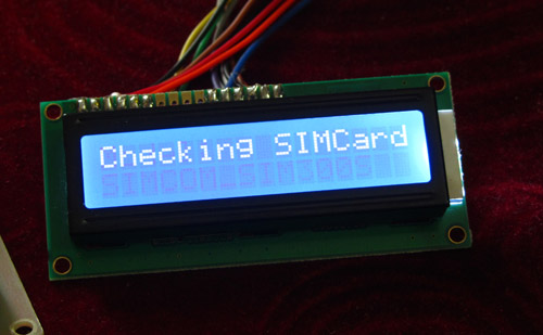
   LCDWriteString("Checking SIMCard");

   _delay_ms(1000);

   r=SIM300IsSIMInserted();

   if (r==SIM300_SIM_NOT_PRESENT)
   {
      //Sim card is NOT present
      LCDWriteStringXY(0,1,"No SIM Card !");

      Halt();
   }
   else if(r==SIM300_TIMEOUT)
   {
      //Communication Error
      LCDWriteStringXY(0,1,"Comm Error !");

      Halt();
   }
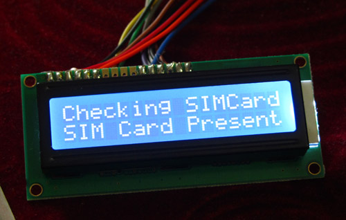
   else if(r==SIM300_SIM_PRESENT)
   {
      //Sim card present
      LCDWriteStringXY(0,1,"SIM Card Present");

      _delay_ms(1000);
   }

   //Network search
   LCDClear();
   LCDWriteStringXY(0,0,"SearchingNetwork");

   uint8_t     nw_found=0;
   uint16_t tries=0;
   uint8_t     x=0;

   while(!nw_found)
   {
      r=SIM300GetNetStat();

      if(r==SIM300_NW_SEARCHING)
      {
         LCDWriteStringXY(0,1,"%0%0%0%0%0%0%0%0%0%0%0%0%0%0%0%0");
         LCDWriteStringXY(x,1,"%1");
         LCDGotoXY(17,1);

         x++;

         if(x==16) x=0;

         _delay_ms(50);

         tries++;

         if(tries==600)
            break;
      }
      else
         break;

   }
   LCDClear();

   if(r==SIM300_NW_REGISTERED_HOME)
   {
      LCDWriteString("Network Found");
   }
   else
   {
      LCDWriteString("Cant Connt to NW!");
      Halt();
   }

   _delay_ms(1000);

   LCDClear();

   //Show Provider Name
   char pname[32];
   r=SIM300GetProviderName(pname);

   if(r==0)
   {
      LCDWriteString("Comm Error !");
      Halt();
   }

   LCDWriteString(pname);

   _delay_ms(1000);

   Halt();
}

void Halt()
{
   while(1);
}
What the Demo Program does?
- Initializes the LCD Module and SIM300 module.
- Check if the SIM300 module is present on the USART and responding properly.
- Displays the IMEI No of the SIM300 Module.
- Displays Manufacturer ID
- Then checks for the SIM card presence.
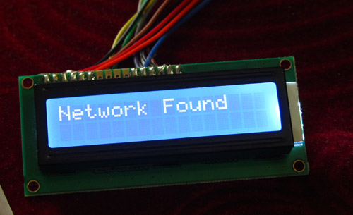
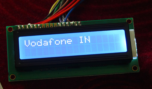
- Searches for a GSM Network and establishes a connection. The sim card need to be valid in order to connect to the GSM network.
- Shows the Network Provider’s name like Airtel or Vodafone.
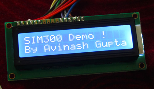
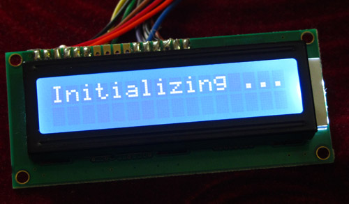
Troubleshooting
- NO Display on LCD
- Make sure AVR Studio Project is set up for clock frequency of 16MHz (16000000Hz)
- Adjust the Contrast Adj Pot.
- Press reset few times.
- Power On/Off few times.
- Connect the LCD only as shown on schematic above.
- On SIM300 Initialization phase if you get error "No Response"
- Check Rx,Tx and GND line connection between SIM300 and the xBoard.
- Make sure crystal frequency is 16MHz only.
- Fuse bits are set as described above.
- Compiler Errors
- Many people these days has jumped to embedded programming without a solid concept of computer science and programming. They don’t know the basics of compiler and lack experience. To learn basic of compilers and their working PC/MAC/Linux( I mean a desktop or laptop) are great platform. But embedded system is not good for learning about compilers and programming basics. It is for those who already have these skills and just want to apply it.
- Make sure all files belonging to the LCD Library are "added" to the "Project".
- avr-gcc is installed. (The Windows Binary Distribution is called WinAVR)
- The AVR Studio project Type is AVR GCC.
- Basics of Installing and using AVR Studio with avr-gcc is described in this tutorial
- General Tips for newbies
- Use ready made development boards and programmers.
- Try to follow the AVR Tutorial Series from the very beginning. (Remember the list spans four pages, page 1 is most recent addition thus most advance)
Downloads for GSM Module Demo.
- Atmel Studio 5 Project for SIM300 Demo.
- Atmel Studio 6 Project for SIM300 Demo.
- HEX File Ready to Burn on ATmega32 running at 16MHz.
- SIM300 Complete Command Set.
Liked this Article ? Want More ?
Well see this !
Help Us!
We try to publish beginner friendly tutorials for latest subjects in embedded system as fast as we can. If you like these tutorials and they have helped you solve problems, please help us in return. You can donate any amount as you like securely using a Credit or Debit Card or Paypal.
We would be very thankful for your kind help.
By
Avinash Gupta
Facebook,
Follow on Twitter.
www.AvinashGupta.com
me@avinashgupta.com
Facing problem with your embedded, electronics or robotics project? We are here to help!
Post a help request.



Nice tutorial for GSM, any idea for GPRS communication tutorial.
Also one more thing, just blur the imei number on the LCD. Since its not safe to show the imei number on web.
nice tutorial avinach
i want to ask about if you will do a tutorial about connecting the sdcard memory
and thank in advanced
Nice…please add the tutorial for GPS.
Thanks for one more great article.
Thanks you liked it ! 😀
Pingback: Sending an Receiving SMS using SIM300 GSM Module | eXtreme Electronics
Hi avinash really awesum tutorials…man….!!
i m working on AVR microcontrollers. I used various development board but really those boards needs to be upgraded… so i m plaining to designed my own development board….
I have no issues with the interfacing any component or circuit….
Just need your help in designing PCB layout…..
I can do that small less complicated circuit but for the huge complex complex circuit..
i dont know but i m worried about it a little….
can u provide me a tutorial on designing PCB layout… in the extremeelectronics style….
i m totally impressed the way u explain things….. just waiting for tutorial on this topic from your side….
Pingback: SMS Based Voting System – AVR GSM Project | eXtreme Electronics
Hello
Nice Tutorial…I am working on GSM Modem SIm300 with 8051 Micro.
When i got message NO DIAL TONE from modem, Micro gets hanged up.I tried reset Command also to reset GSM Modem but with no success.
To solve it i gave a delay of approx 2 minute. After that it work properly. Any idea to solve it without using delay.
One problem arises. When i made a call to only one number again and again, it works properly. But when i call to two numbers one after the other in a loop, it works only for one time and after that micro gets hanged.
Any idea to solve above two problems.
Hi,
I am impressed the way you taught things , where i can get the whole code.
I have simcom 908 and i am planing to do the same and the way you explain is really very helpful.
With best wishes
Thanks!
Please look clearly at the article once again and you will get a heading called “Downloads” under it their it a link which clearly states the download!
what will be the difference if we are using an arduino board?
@Diya
lots of difference and I don’t have the time to list.
Hi Avinash,
you are a killer man…….you are just fantastic thnx a ton or this amazing tutorials….this thing was not so easy before…….you are amzing…hats off…:)
@Abhilash
Thanks ! 😀
Hi Avinash,
I bought one RF ID reader and one GSM modem from ur website.
Is it possible to connect these two with one UART ? Bcoz I am using ATmega32. So pls tell me how to use it.
Better use Atmega324 having two usart..!!!
You are right,but cost of Atmega324 is double than Atmega32.So it is better to use Atmega32 with software USART. Thank
you.
Yes Parminder, it is certainly possible to connect one RF ID and one GSM modem with one Atmega32.For this you can hire a developer or give it to a consultancy
firm.Further,we can help you.Connect one of device with hardware USART and another one with software USART.A soft USART library helps in connecting more than one
serial devices to a MCU which only has a single hardware USART. For example you may connect a GSM Module and GPS Module at the same time to a low cost MCU like
ATmega8. Otherwise you have to look for a MCU which has two serial ports, but that will be a costly option. So this library helps you emmulate a second software serial
port! Thank you
Hi Gaurav,
Thanks for your response.
Where will I get this Software library for serial port ?
Pls reply soon.
Thanks in advance.
Parminder,you have to made the software library by yourself or you can get this made from a consultancy firm. Thank you
@ it is certainly possible to connect one RF ID and one GSM modem with one Atmega32.For this you can hire a developer or give it to a consultancy…..
i would like to pay for Atmega324….instead..
why to make things complicated when we can actually minimize the complexity…
Parminder bro i still suggest atmega324…rest up to u….
Thanks brother. I will try to do this.
@Gangster, you are confusing “smart” solution with “complication”
If all engineers start thinking like you, we wont get multimedia branded mobile @Rs. 2500/-!
Which few years back, used to costs Rs. 25K!
And mobile calls would have never been be free ! And in reach off all !
Even if you consider a product with minimal life time and produced only 100 units. That will save you Rs. 20000/- ! (considering Rs 200 over head on each product).
And I wrote a soft USART in 2 hours flat! So I saved Rs. 20,000 in just 2 hours !
@avinash
well i thought he was planing to make a single piece and to hire a developer and give him his consaltancy for the same will cost him more than a 324.
if he can do it by his own then there is no better option than using a soft usart.
Actually I thought he is a professional guy that’s why pointed him a professional solution, I did not knew if he was some child playing with a toy ! Ha ha one piece ? Why would any one make 1 piece!!! At least if he is in the field, he may face similar situation atleast twice ! What do you say ?
@avinash
Which design software do you use?
@Abdul
To design what? Schematic, Layout, Images, System Modeling or Design Software?
@avinash
like proteus or any other To design
Schematic
@avinash
like proteus or any other To design
Schematic.
I want to test program without any hardware and in proteus GSM modem is not available.
Abdul,it is not possible to test program without any hardware.Thank you.
Sir,where can i download sim300.h headder file
Can u please suggest any links for downloading the headder file…….
Purchase SIM300 kit with xBoard v2.0 from our store to get the files.
http://store.extremeelectronics.co.in/xBoard-v2.0.html
http://store.extremeelectronics.co.in/GSM-GPRS-Modem-SIM300-KIT.html
Sir,
I am working with sim900 module and this code of sim300 is not working onto it, as it does not give any response. Can you please tell me what necessary changes should be made to work with sim900.
Thanking You
Sumit Sinha
@Sumit Sinha,
This code works perfectly on SIM900 also. You have having a messy hardware. To avoid wasting time (both yours and ours) and to do something magnificent (instead of dull days of disappointments ) please get a ready made hardware. We sell it for Rs. 4000 tell us if you are interested.
Thank you.
•On SIM300 Initialization phase i get error
“No Response”
i have checked Rx,Tx and GND line connection between SIM300 and the Board.
? crystal frequency is 16MHz only.
?Fuse bits are set as said
i m using atmega 32A
while using programer advantech labtooluxp i selected atmega32/L(there is only one option)
i can’t get any pulse on crystall oscillator
how i can move forward..plz help
Please run on xBoard v2.0 only
http://store.extremeelectronics.co.in/xBoard-v2.0.html
my board is working proper i hve doubt of progarmmer…i m selecting atmega32/L instead of atmega 32
will it make any diffrence?
Sorry if you are not interested in the solution, then you can have fun with your troubles. I am least interested to join your fun!
i need full working project with all hardware and software . how much it will cost?
xBoard v2.0 @ Rs. 1264
http://store.extremeelectronics.co.in/xBoard-v2.0.html
SIM300 KIT @ Rs. 1699
http://store.extremeelectronics.co.in/GSM-GPRS-Modem-SIM300-KIT.html
Shipping extra.
Hello Mr.Avinash
Thank you very much for your website.
I have a question :
I am using SIM900 instead of SIM300.unfortunately i got “NO RESPONSE” response and the microcontroller stops on this response and dont move further in.
Is the problem with SIM900?it means that if i use SIM300 the problem will be solved?or the problem is on other part of circuit?i made the circuit exactly according to your above schematic on a breadboard.
Pleae advise me in this regard.
Thanks and best.
@Kamran,
In your childhood you must have been taught time is money so you should not spend valuable time, please use exactly same hardware as shown to avoid problems. Do not use breadboard for making circuit, use development boards as the aim of the project is to learn GSM interfacing and NOT bread boarding.
Hello Mr.Avinash
sir i am working on a project on gsm modem using atmega16 avr micro controller but i want to use gsm modem in auto-answering mode so when i call i will automatically receive then call . i just want to know how i am going to do this or how can i program the micro controller for this sir plz reply .
hey avinash i want to know what is the frame size we require for sending a message from sim 300 that is gsm module …and where i can find total information about it ..plz help
@Ronil,
I could not understand your question.
Hello..!!
I am using atmega16,sim300 module.
internal crystal frequency is 8Mhz, and baud rate is also set accordingly , and connections are also right, then also its showing “No Response ” on lcd..
Please help, am stuck on this from 1 week..
please do help..!!
thank you.!!
@ Yogesh
Use the same hardware as shown above to solve your problem.
how to connect zigbee and rfid both to single atmega 32 micro controller
@Praveen,
Use soft USART.
how i can buy SIM300 board ??
online on this site
could you explain that while checking echo why u are comparing the length of command AT with udataavaialble()
//Wait for echo
while(i<10*len)
{
if(UDataAvailable()<len)
{
i++;
_delay_ms(10);
continue;
}
else
{
//We got an echo
//Now check it
UReadBuffer(sim300_buffer,len); //Read serial Data
return SIM300_OK;
i am unable to understand this part
@Ujjwal,
That’s because same number of bytes which are written to sim300 are echoed back
but 6 byte response will echo back
and no of bytes written Is of only 3 bytes AT and
Its task is to remove the echo only not the response. Response is checked latter.
CR
that means gsm sim300 woll always echo back the same command as it is sent to it and we just removing it
means it is just one of function of sim300 to echo back
just like other function as to send response,etc
have i understood correctly
if yes thanks in advance
yes u are right,in echo state as we give a single command(like A) there will be response from modem A.
u can test this by communicating gsm modem by computer
i’m fan of all your projects and interesting tutoriels on ExtremeElectronics web site,could you please answer me how can i buy the SIM 300 moduel from india cause i have no idea haw to do exactly in tunisia … , god bless you and thank you very much Mister Avinash. 🙂
u can get online on extreme ele.site
hello avinash sir,
i have made this project and i want to add a extra hardware that is to display the message send by mobile
on led matrix .
so pls sir guide me in writing program for it pls sir i need its my final year project
pls reply me
Hello,
I am using atmega8 for interfacing with the gsm module.I wrote the code in bascom and generated the hex file. I want to know the software required to dump the hex code into the controller.can u please suggest a software for that.Is it possible to use other software such as hidbootflash for dumping??
Thank you
@Mahi,
Please see this
https://extremeelectronics.co.in/xBoardMINI2/docs/Programming.htm
Sir, instead of using AVR dev board in connection sim300, can we use Arduino board?
Yes why NOT? You can use Arduino board, but then you get zero help from this page this page doesn’t describe that !
Sir,
Thank you very much for your website.
I have a problem..
on flashing the file it shows -Mismatch at location 0x00000000 .
what should i do??
please help.
@Deepika,
more input is required from your side to get to any solution.
So it is suggested that you move this discussion to our forum.
http://forum.extremeelectronics.co.in/
Hi sir,
i am doing one project with sim 300 gsm module.here gsm module conecting to pc ok.but is conected to microcontroller(pic16f88) is fails.micro controller sends the AT command and Gsm module sends “PU”.sir what the problem pls help me.
HELLO SIR
I JUST WANT TO KNOW IF YOU HAVE MADE A SOFTWARE UART PROGRAM OR TUTORIAL AVAILABLE ON YOUR SITE FOR US TO LEARN ?, I HAVE SEARCHED YOUR SITE AND WAS NOT ABLE TO FIND ANYTHING RELATED SOFT UART. COULD U PLEASE HELP US WITH SOFT UART,?
Kindly sir tell me what changes we have to run this code at sim900 gsm module.
Kindly help me.
@Faizan Mehmood.
From where have you purchased the SIM900?
hiii Mr.avinash,
can u please help us with the GSM code for AVR controller…. we dnt have any idea abt the programming and the header files…..
Hello Sir ,
I wants to upload any data coming from any serial port on sever (dropbox) by using atmega16 and sim900 .and also read the response of sim900 . sir please can you help me.
Hi Avinash,
I am planning to purchase SIM900 kit from your website. Only thing I want to know that will the code for SIM300 will work for SIM900 or any change in Software or Hardware is required?
is this code is also compatible for sim 900 kit
Hy All!
I want to interfacing a SIM900A module with an Atmega16 MCU.
My question is quite simple: What does it mean ” we have implemented a interrupt based buffering of incoming data.”
this bufffer is the MCU’s UART Buffer?
Implementation of SIM300Cmd, in this u have multiplied len by 10 so suppose my command is 7 bytes (inclusive of null char ) then total the loop may wait for 700ms right?? so is there any logic beyond tym we have to wait for echo or is it simply 100 tyms the bytes??
plzz provide all the three header files..usart.h, sim300.h, lcd.h i am unable to find it.
Sir,
you made embedded programming EASY … reading your tutorials are like being in adventure 🙂 🙂
I am getting “null” instead of “Test” in sending msg
but in code its “Test” only
Is this some sim problem??
sir we cant download sim300.h and usart.h file.i have successfully download lcd.h file.please provide a link for downloading the header files.that must be more helpful for our project.
@Amal Bhaskar,
Yes sure we can help you by providing you all the files, but first you have to share this page on Facebook and send us the link to your Facebook profile.
Hi, can you send me the sim300.h and usart.h file if you have it?
plz send it to phantom_0323@yahoo.com
thank you
Is it possible to modify this code for using with gps modules?
hi Avinash
how do i interface sim 300 module and fingerprint module to the same xboard mini. is it possible?
plz give some replay
Hello,
Intresting article.
Please can you share the information on what to look for when connecting an GSM to Controller.
Rx of GSM to Tx of controller
Tx of GSM to Rx of controller
Gnd to Gnd
Any other important to look for?? I can send an SMS but cannot read the text ” OK” using controller. I can read the values using USB but not when connecting controller.
Please suggest
Thanks
Kumar
Hello Sir, Im using this library with tuxgraphics’s ENC28J60 library. The ENC28J60 library works. I wrote:
gsmerror = SIM300Init();Then I printed it on Network and gsmerror is 253. It doesnt matter if I connect GSM module to power or not gsmerror is 253.
Hello sir, What are the differences when we use sim800 GSM Module? can we use the same header files?