Here is a project for beginners using Atmel AVR ATmega8. The project uses some techniques that are very useful for designers to learn and utilize.
- Alphanumeric LCD Module Interfacing.
- 4×4 Keypad interfacing.
- PWM Control of LED (Used to dim the back-light of LCD, like in some Nokia Phones)
- Basic Circuit design for AVR MCUs
- Connecting relays and other current demanding devices.
- AVR Studio and project management.
- compiling using free avr-gcc compiler.
- Using eXtreme Burner – AVR to burn hex code to AVR MCU.
NOTE:
Don’t waste time finding each part running from shop to shop. Get all the parts with exact specification in a ready to use kit! Purchase ATmega8 based smart code lock KIT.
 |
Fig.: ATmega8 Based Code Lock |
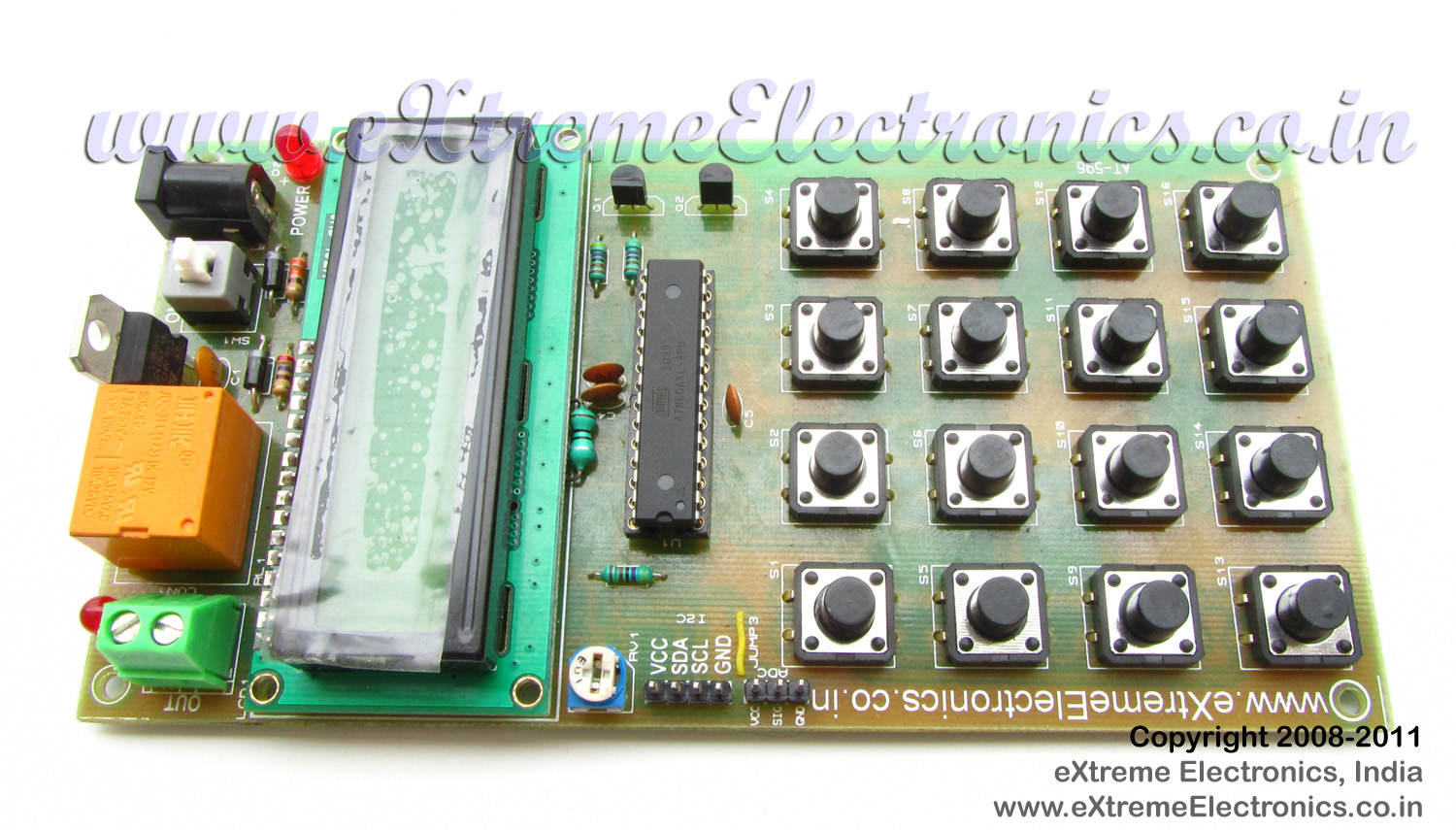 |
Fig.: ATmega8 Based Code Lock Project |
Functions of the Project.
This device can be used to code protect any electrical device (like an electronic door, lock or safe). The user must enter a correct password to gain access. The password is entered using the built in 4×4 keypad matrix. The main LCD Module is used to display messages to the user. As soon as correct password is entered the relay is activated. This is indicated by a LED which is placed near the relay. The relay remains on as long as the user wishes. You just need to press a key to deactivate the relay.
After typing four digit password you must press the "OK" button (S8). At anytime you may press the "Cancel" key (S12 )to clear the input (e.g. when you enter any incorrect digit)
The smart code lock has the feature to change the password too. For this enter a special password which is ‘0000’, as soon as the system receives this special password it switches to change password mode. Here you need to enter the old password to gain permission, then enter the new password.
The smart code lock also support power saving feature. The backlight of LCD turns off automatically when the system is idle for few seconds. The cool thing about this is that it uses PWM to control the brightness of LCD Backlight. So the dimming is very smooth and it is like those used in many mobile phones.
Making it yourself!
You can fabricate the circuit on any general purpose PCB or breadboard. The schematic and the BOM (Bill of Material is given below). To save you from lots of trouble we have made a quality PCB of the same! If you purchase the PCB, you just need to solder different components at their proper place on the PCB and you are ready to go.
Burn the HEX file (given at the end of article) to the ATmega8 MCU using any suitable programmer and plug it into the 28 PIN IC Socket.
After assembling the circuit power it on using a 12V 500ma Center Positive DC Wall adaptor (you can use one that is used for mini TVs or Game Consols or Your DSL Modem). Adjust the variable resistor RV1 (just below the LCD module, on the left side, yes the blue thing!) until the LCD Shows some text.
Schematic for ATmega8 based Smart Code Lock
 |
Fig.: Complete Schematic (Click to Enlarge/Print) |
Bill of Materials (BOM)
Part List |
||
| 01 | 330 ohm resistor (2 Nos) | R3, R5 |
| 02 | 4k7 Resistor (3 Nos) | R2, R4, R6 |
| 03 | 200 Ohm Resistor | R1 |
| 04 | 0.1uF Ceramic Disk Capacitor (4 Nos) | C1, C3, C4, C5 |
| 05 | 1N4007 Diode (2 Nos) | D1, D3 |
| 06 | LED 5mm Any Colour | D4 |
| 07 | ATmega8L-8PU General purpose 8 bit MCU | U1 |
| 08 | 7805 Voltage Regulator | U2 |
| 09 | Power Connector 2 Way | CON1 |
| 10 | PCB Mountable Relay | RL1 |
| 11 | On/Off Switch | SW1 |
| 12 | DC Socket | X1 |
| 13 | 16×2 LCD Module | LCD1 |
| 14 | 10K Preset (Blue Plastic POT) | RV1 |
| 15 | 28 PIN Narrow IC Socket | |
| 16 | BC548 Transistor(2 Units) | Q1, Q2 |
| 17 | Push Buttons (16 Units) | |
| 18 | ATmega8 Based Smart Code Lock PCB | |
Firmware Source Code
The firmware source code is written in a professional was that may seems confusing to a n00b programmer. The thing is that every piece of related functions are stored in a separate source files. That means the the project is composed of several ‘C’ source file. Each C file has set of related functions (like LCD Interfacing Routines or EEPROM Access). You must use AVR Studio as a project manager and WinAVR as compiler. Both the software must be installed in your PC. In the project folder their is a file with name "code_lock.aps", this is the main AVR Studio Project file. Load it in AVR Studio. You can see the various files that are part of the project in the left hand pane as shown below. Double click any file to load in the editor. After a file has been loaded in editor you can view and change it.
 |
Fig.: AVR Studio Main Window |
The highest level file which contains the main application logic is "code_lock.c". This file contains the main() function. The rest files are lower level files that provide service to the higher level files. If you want to customize the firmware you can easily do so by editing the file "code_lock.c", in most cases you do not have to touch the other C files.
Building the Binary from the source code.
You need to convert the high level human readable source code into machine language so that the AVR chip can execute it. The complete process of this conversion is called "Building" (yes, compilation is one of the steps of building). After build is complete you get a file called "code_lock.hex" which is placed inside a folder called "default" inside the project folder. You just need to program this hex file to the ATmega8 MCU using any suitable programmer .
 |
Fig.: AVR Studio Build Button |
You can build the project using the "Build Active Configuration" button as shown above. You can also hit F7 button or Select Build from Build Menu.
The Fuse bits must be set as follows. Consult your programmer software for more info.
- HIGH=D9
- LOW=E1
Please note that the above is default for ATmega8, so if you purchased a new chip then you do not need to change them.
If you are new to AVR Studio and WinAVR Please read the following article carefully.
avr-gcc program for Code Lock
/******************************************************************************

Title:

   ATmega8 Based Smart Code Lock.

Description:
   A simple project for making a digital code lock. The main input device is
   a 4x4 Matrix Keypad. The main output is a 16x2 LCD Module.

   The user has to enter a correct password to gain access. On receipt of
   correct password the relay is energized, which can be used to operate

   and device like an electronic door.

   Their is facility for changing password.

   For More information visit
   http://www.eXtremeElectronics.co.in


Author:

   Mandeep Tiwary under supervision of Avinash Gupta.

   mandeep@eXtremeElectronics.co.in
   avinash@eXtremeElectronics.co.in

Copyright:
   eXtreme Electronics, India 2008- 2011

Notice:
   No part of this work can be copied or published in electronic or
   printed form without proper permission from the Original Creators.

   ONLY INTENDED FOR EDUCATIONAL, HOBBY AND PERSONAL USE.
   COMMERCIAL USE IS STRICTLY PROHIBITED.

Disclaimer of Warranty.

   THERE IS NO WARRANTY FOR THE PROGRAM, TO THE EXTENT PERMITTED BY APPLICABLE LAW.
   EXCEPT WHEN OTHERWISE STATED IN WRITING THE COPYRIGHT HOLDERS AND/OR OTHER
   PARTIES PROVIDE THE PROGRAM “AS IS” WITHOUT WARRANTY OF ANY KIND, EITHER
   EXPRESSED OR IMPLIED, INCLUDING, BUT NOT LIMITED TO, THE IMPLIED WARRANTIES

   OF MERCHANTABILITY AND FITNESS FOR A PARTICULAR PURPOSE.
   THE ENTIRE RISK AS TO THE QUALITY AND PERFORMANCE OF THE PROGRAM IS WITH YOU.
   SHOULD THE PROGRAM PROVE DEFECTIVE, YOU ASSUME THE COST OF ALL NECESSARY
   SERVICING, REPAIR OR CORRECTION.

******************************************************************************/

#include <avr/io.h>

#include <inttypes.h>
#include <util/delay.h>

#include "lcd.h"
#include "keypad.h"
#include "user_interface.h"
#include "password_manager.h"


//LCD Backlight i/o configuration
#define LCDBL_PORT   PORB
#define LCDBL_DDR DDRB
#define  LCDBL_PIN   PB1

//Output relay i/o configuration
#define RELAY_PORT   PORTC
#define RELAY_DDR    DDRC

#define RELAY_PIN    PC0


//Simple Delay Function
void Wait(uint8_t n);

//Relay Control Functions
void RelayOn();
void RelayOff();


//System Functions
void SystemInit();

void main()
{
   uint16_t password;

   //Initialize the system
   SystemInit();

   while(1)
   {
      password=InputNumber("Enter Password");

      //Match Password

      if(password==ReadPassFromEEPROM())
      {
         LCDClear();
         LCDWriteString("Access Granted");

         //Now Activate Relay
         RelayOn();

         Wait(15);

         LCDClear();
         LCDWriteString("Press Any Key");

         //Now wait for any key
         while(GetKeyPressed()==255)
         {
            _delay_loop_2(10);
         }

         //Now DeActivate Relay

         RelayOff();

         Wait(2);

      }
      else if(password==0)
      {
         /*

         If user enters 0000 as password it
         indicates a request to change password


         */
         LCDClear();
         password=InputNumber("Old Password");

         if(password==ReadPassFromEEPROM())
         {
            //Allowed to change password
            uint16_t NewPassword;
            NewPassword=InputNumber("New Password");
            WritePassToEEPROM(NewPassword);

            LCDClear();
            LCDWriteString("Success !");

            Wait(15);
         }
         else

         {
            //Not Allowed to change password
            LCDClear();
            LCDWriteString("Wrong Password !");

            Wait(15);

         }
      }
      else
      {
         LCDClear();
         LCDWriteString("Access Denied");
         RelayOff();

         Wait(15);
      }


   }


}


void SystemInit()
{
   //Set LCD Backlight Pin as output
   LCDBL_DDR|=(1<<LCDBL_PIN);

   //Set Relay Pin as output
   RELAY_DDR|=(1<<RELAY_PIN);

   //Wait for LCD To Start

      _delay_loop_2(0);

      //Now initialize the lcd module
   LCDInit(LS_NONE);
   LCDClear();
   LCDWriteString("    Welcome !");

   LCDBacklightOn();

   //Check if the EEPROM has a valid password or is blank
   if(ReadPassFromEEPROM()==25755)
   {
      //Password is blank so store a default password

      WritePassToEEPROM(1234);
   }

}

void Wait(uint8_t n)
{
   uint8_t i;
   for(i=0;i<n;i++)
      _delay_loop_2(0);
}
void RelayOn()
{
   RELAY_PORT|=(1<<RELAY_PIN);
}


void RelayOff()
{
   RELAY_PORT&=(~(1<<RELAY_PIN));
}
PCB for AVR Based Smart Code Lock
We have made a high quality PCB complete with solder mask, component layout, tinning (for perfect soldering) on a FR4 (highest quality) material. You can purchase the same from our store. Your purchase help us create more interesting tutorials like this one and keep this site running.
You can purchase the PCB from the following link
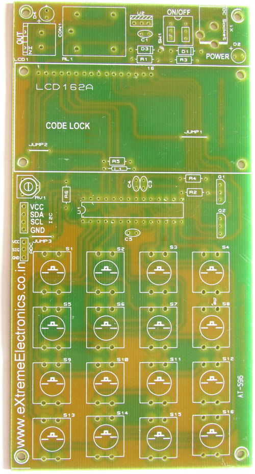 |
Fig.: Code Lock PCB(Purchase Here) |
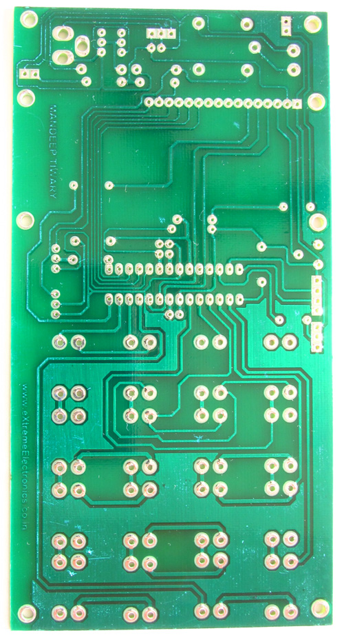 |
Fig.: Code Lock PCB (Purchase Here) |
Purchase Kit
Don’t waste time finding each part running from shop to shop. Get all the parts with exact specification in a ready to use kit! Purchase ATmega8 based smart code lock KIT. And help us create more and more free AVR projects.
Downloads
- Complete AVR Studio Project (ZIP File)
- Precompiled hex file for burning to ATmega8 MCU
- PCB Layouts in PDF, DOC and PNG Formats.
Credits
Original Concept, Design, Photography, Image Editing and Writing by Avinash Gupta
PCB Designing, Junior Programming , Prototype fabrication and testing by Mandeep Tiwary.
As always, good job, Avinash!! Making it easier for everybody!! Thanks to Mandeep Tiwary, too!!
Again an amazing job, So many things in one project to learn.
Thank you for guiding Mr. Mandeep and publish. Really your site become richer day by day !
yet not found the PCB in your store.
expecting more sensors in your store like humidity, hall effect, etc.
@Uttam Dutta
Thanks.
I have the humidity sensor with me but not yet cataloged in store. The reason is that unless I have a working code and tutorial, I do not sell the stuff. Unlike many who just import from Olimex or Sparkfun. Uses their images and give absolutely no info that a beginner can actually use it.
Just filling up the catalog is very easy that way!
wow so much learning in just one project thank u sir, for giving us such valuable information without any reward, may god bless u,..
@Uttam Dutta
PCBs available for sale!
You can purchase here.
http://shop.extremeelectronics.co.in/product_info.php?cPath=50&products_id=841
Readers who own an active electronics blog can get the PCB free of cost(free shipping too!) Contact me via Comment System on this page.
This is available to readers living in most part of the world. But international deliveries can take upto 1 month to reach.
I will dispatch them only when I have about 20-30 free PCB request on my hand so please keep patience.
The only requirement is that you have to post one article on your blog which describes your experience in making the project with pictures and videos. This must be done within 15 days of receipt of the PCB, other wise you will not be able to take advantage of future Offers!
Dear Sir, I have one clarification. You have code for atmega8. We want to use atmega16/32. Shall we use the atmega8 code and compile it in AS5 for atmega32? Does the hex file work without error in 16/32?
hey av just wanna know the eeprom you are using on the project is an internal or external one,because couldn’t find any eepromm chip on the pcb.bt the sda,scl pin-outs are there(i can see them).
your project is well-documented,as always,u’r amazing.thnx.
@Sayantan,
We have brought out the I2C Port so that we can interface whole lot of addon to this boards like PORT expanders, RTCC, Temperature sensors, Accelerometers etc. We have also brought out the USART Port so that we can connect RFID Readers, GSM Modules, Humidity Sensor etc. The Idea is to use the same PCB for more projects!
Hi sayantan….
This project is running using internal eeprom. And it have also (I2C) connector.if you wish you can also connect the external eeprom.
ok,thnx for the rply both of u.u are talking about port expanders,can u suggest a tutorial for that,i mean the i2c routines or functions for i/o expanders.that would be a great help.thnx.
I’ve read the eeprom.c file and eeprom.h file. From that i understood that 1st two digits are stored in ‘0001’ block and next in ‘0000’ block.
My doubt is
1)in systeminit() function while storing the default password
if(ReadPassFromEEPROM()==25755)
what is this 25755
2)how many such (‘0000′,’0001’,’0002’……) blocks are there in Atmega32 or 16 .
Please reply………..
correct me if any of my conclusions are wrong
thank you in advance… 🙂
it is the value you get when you multiply 255 by 100 and add 255 in it. It is because hunderth and thousandth digit are stored in address 1 while tenth and unit place are stored in address 0. The value 255 corresponds to hex FF which is the blank erased value of EEPROM cells.
Hope it helps. In Atmega32 i think 1024 (1KB) cells are available. I am not sure so see the datasheet.
thankyou for your reply. now i understand.
and yes it us 1024 for atmega32 and 512 for atmega16. i found this after posting the comment.
Actually, my project is an flawless attendence system for universities with RFID technology. so i have to store the tag values of all students in eeprom.
what do you recommend – internal memory or some external memory like a memory stick?
thank you in advance 🙂
great job avinash!
i want to ask that will this code run perfectally in atmega16 because i want to this on atmega16.
hello, okay?
First the design is very good, congratulations.
I am new to programming, but managed to ride the
project.
But I can not put the correct password, it has some
secret?
I type the password reset to 0000, but he asks
old password, and I can not access it.
Can you give me this password? or has some way to get
this password in programming?
Sorry, but not found.
Thanks
Andre Giovanni
Hello,
The default password is 1234
when asked old password. Please enter “1234”
It would be nice if you can share photos and videos of the project with us.
hmmm, ok
yeah, I tried 1234 and it did not work, I must be some problem with the
I imagine the order of the keys, I’ll check. I’ll post pictures in the future,
Thanks
Nothing words to say about your work, really amazing work done by extreme electronics,definitely one India will proud about this site,Great work……
@Murali
Thanks!!!
Le mot de passe par défaut est 1234 ca marche pas
Pouvez-vous me donner ce mot de passe
svp
Can you give me this password 1234 no work
j’ai essayé 1234 et ça n’a pas fonctionné tout et bon m!!!!!
@ Jack,
Le problème est que vous êtes en supposant une certaine autre touche ‘1 ‘alors il peut être ‘9’ ou ‘7 ‘ou ‘3’
j`ait fait le même pcb me ça marche pas le code 1234
le clavier (même clavier) tout et bon me !!!!!
wrong password tous jour !!!!!
e de mois merci (send me good hex ) plz…
jack
ci quoi s1 s2 s3 de clavier ci équivalent 1 2 3….*
merci
jack
http://www.alsatel06@yahoo.com
I am from Iran and hex file so I can buy it in the hex file is limited
If possible, please send e-mail address thanks to hex file
farshid.star72 @ gmail.com
Can you tell me the exact dimensions of the pcb.When i print it out the MCU does not match the pins with the pcb.
i made the picture with 99% zoom and the board came out 8cm / 15.6 cm(the MCU pins are aligned almost perfect).Is this correct?
@Sekai,
very simple page scaling problem. Select Correct paper size in printer driver and the printing app (ex MS Word)
The relay should be in mirror.My relay is the other pin.If i leave it like this CON1 will always stay on.
le code hex cas marche pas attention
1.2.3.4 ????
le code de ATmega8 Based Smart Code Lock et 7894
merci
Hey I noticed that you are not using a crystal in this project. Are you using the internal clock? Is there any specific code to write if I want to use the internal clock or I have to make adjustments with the fuse bytes?….Please guide… Happy New Year!
Lock code not 1234. If you have the correct code for this is the hex code in your site. Thank you. (j.f in iran)
hi friend
oldpassword=7894
thank you very much.
it is very good ,but when new pass=0000 chenged then not cheng password.
Hi..
Pls tell me where to changethe code for using it in a 8 bit mode lcd.and atmega 32
can you send us the logic used in the program…you had cused the header file in program,but we couldnt find it anywhere in the program….please send us the detailed info abt the whole project asap..
I am using AVR5 and i loaded all of the files that you have provided into my project. But when i click build i get two errors. They are both from the eeprom.c file.
1. ‘EEMWE’ undeclared
2. ‘EEWE’ undeclared
What do you think i can do to correct this issue.
HI john, i want to answer your question, soryy to born late, i just found the solution, maybe when you want to rebuild the code, you change the microcontroller kind. so the master write enable and write enable command is different . im use atmega 328p and change EEWE to EEPE and then EEMWE to EEMPE. the warning then disappear and build is success. now this code can run on my atmega 328p
Sir, I am also trying to make this project. I completed hardware. S8 is for enter and s12 is to clear.These two switches are working. But when i trying to enter password, it shows access denied. PLZ tell me correct password and and the corresponding keys for that password like S8 to enter & S12 to clear.
#include “eeprom.h”
#include “password_manager.h”
void WritePassToEEPROM(uint16_t pass)
{
EEPROMWrite(0000,(pass%100));
EEPROMWrite(0001,(pass/100));
}
uint16_t ReadPassFromEEPROM()
{
return (EEPROMRead(0001)*100 + EEPROMRead(0000));
}
Can you please post the complete code for 128×64 graphical lcd interfaced to ATMEGA32 to display a string of letters, numbers and special characters. I am using studio4. Please give assistance of header files also.
@Lavanya,
I think this would be useful for you
https://extremeelectronics.co.in/avr-tutorials/interfacing-ks0108-based-128×64-graphical-lcd-with-avr-mcu/
HI all.this article very nice and carefully assembled,the pass is 1234 corresponding to 4x4keypad(KEYPAD-SMALLCAL in ISIS). But i have a question, what does it mean the codeline uint8_t key[]=”####”;
in file user_interface.c
Thanks for reading and answering to my question !
if can, plz reply to my email as well !!
Hi… this is very nice article,
i have some question,
1. What have to change to make password more than 4 digits?
2. If want to limit 3 times input password, more than 3 times with relay activated for sirens, how to do it? What have to change?
To be honest, I’m not clear in avr studio,
Please kindly reply,
Thank you.
Hello Avinash sir,
i want to know which pins of Atmega8 are to be used for ISP Programming,
thanks
-aashutosh
Aashutose for your convenience, we have made a video tutorial .Please see this http://www.youtube.com/watch?v=4dNWJkqxUS0&feature=player_detailpage#t=574s
thanks a lot gaurav,
the video was very helpful.
i already purchased your atmega8 smart code system project and i assembled that as per your instruction then it was not working ….. and how much input power input is needed.. pls tell me
Can you please explain what do you mean by NOT working? Does that means its not getting powered up? By what means you are supplying the board? Whether you are using a battery or DC Adaptor? What is the voltage supply of then and the supply polarity?
what is the input voltage to the avr atmega8 smart code system… tell me…pls
@Sandy,
Please don’t do the height of drama! Its clearly written in the tutorial above !
what is the correct passward with switches
Guys
This is a great project ..Works perfectly as described. I ordered a PCB, received it day before yesterday ( fast shipping) . Completed it yesterday …Didnt work on first instance , but after thorough cheking of joints worked !!! as described . The ONLY thing is the PASSWORD is not “1234” but its “7894” as stated by someone above in French…U can change it by pressing “0000” and then adding “7894” as old password ….choose a new one then.
Thanks Avinash for a great work !!
Regards
Sir, I am also trying to make this project. I completed hardware. S8 is for enter and s12 is to clear.These two switches are working. But very sorry to say the corresponding keys for that password is not clear like S8 to enter & S12 to clear.Please tell me which is key1,key2 etc.
Hi.
you haven’t mentioned polarity of the capacitor.Please do tell.
Thanks
@Hassan,
Which capacitor?
What have to change to make password more than 4 digits?
Great job
Can you tell how i can store and second password??
I want one for lock and another for unlock
Thank you
would like to request a proteus schematic design of this project.my mail is kasbesh@gmail.com
Good Idea, poor concept. Here’s the problem: your keypad needing to be in the ‘unsecure’ area and your activating device (relay) are on the same board. Anyone can just open up the lid, jumper the (-) relay coil to ground, and access is granted, w/o a password.
Electronic Locks need to have only a communication port with the keyboard and LCD in the unsecured area. This unit must then talk to a unit in a secure area to activate the ‘unlock’ signal. Otherwise, see paragraph 1.
thank you for your job Avinash..i wish good luck for you.
relay is 12v or 5v ..?
12v
sir , i purchased smart lock pcb board in that relay connection is different from the above design why…?
HI. please
What have to change to make password more than 4 digits?
@Joseph,
Have to learn programming and then go through the code, understand it, then formulate some solution then apply the solution.
I am not getting 12v output….. But led is glowing after entering the password.. Pls help…?
sir can we make it on atmega32
When I connect this circuit LCD only show black box. What is the reason of this and how can I solve it? Thanks in advance.
Hello sir,
I want purches this project kit. all above reply are good..but the problem in old passward?. I have making this project as digital lock. i have replace relay by Electronic lock( stepper Motor). tell me changes in programming. also tell me.. when i enter wrong passward 3 times then buzzer will be ringing.
plz tell me. After this solution i want 20 project kit.
plz sir.
my email id: dk.dhanu9@gmail.com
what are the out put devices are sutable for this project.
Hello
First thanks for the code, I have made my own hardware and trying to use the code (downloaded and build with AS4),build was success but it is not working. when i flashed with the readily available hex file in the site. it is working fine.
could you please let me know do we need to do any other modification..
thanks in advance
regards
Logu
Hi Avinash,
I want to implement an electronic safe lock using the Atmega32A microcontroller, 16×2 LCD panel, 4×3 numeric keypad,and a solenoid. Can the same coding be used? If not could you pls tell me what are the necessary changes.
Thanks.
@Niranjan,
Sorry but we don not do anything for free, so I don’t have time tell you about changes or anything else. Sorry.
Hi avinash,
I want to write c program for Atmega32A microcontroller to function as a safe lock.I tried working out the program and all are working fine except the access denied portion for 3 consecutive wrong password entry.
I really need help. Could you pls help me?
Is it possible to do modifications in the above program.
Thanks.
good day, you can send parts to Czech Republic:
//LCD Backlight i/o configuration
#define LCDBL_PORT PORB
why used “PORB” instead of PORT B?
can u plz answr my qstian plz
can i use the same code 4 atmega32
Sir,
If i use a 24 v relay in place of a 12v relay will the circuit work
@Susmit Sarkar,
Why ? don’t you have money to buy a 12v relay?
took this Thread to a thesis project. Urgently need to describe the scheme, I would like to ask you to help me with this. example:
“Power is supplied to the terminal PWR, through a given diode is supplied to the regulator, with him through the display goes to the power controller and the power indication.
Transistor VT1 collected backlight is performed on the controller to perform saving mode. “
Thanks for the project Avinash! made it work!
Although I used correct fuses D9E1 for internal clock (1mhz) in my atmega8 I had to use 8Mhz in Makefile (I’m using WIN AVR) to make it work. Why do you think it won’t work if I use 1 Mhz in makefile?
if this could be used for atmega16? and burn .Hex with avr studio?
@Yudy
No this cannot be used with ATmega16 only with ATmega8
why cannot to apply in atmega 16?
but i try in proteus using atmega 16 worked
What if I want to change enter key in keypad matrix…
whereas that now is the “B”
Good Job!
Could you please explain the purpose of ADC, I2C and J3?
Also, if I want to connect a GSM to the system, how can I do that?
@Anisha,
They are just connection points from the pins or MCU. That means they simply make available those pin of MCU on male header pins. If the user want those pin he/she can tap it fro those headers.
How can we interface the gsm to send us a message when a wrong password is entered? Could you mail me the program in case you have it?
anisha.kandoi@yahoo.com
Thanks in advance! 🙂
“Morning sir..how to set fusebit..??thank’s for your help..):
Nice work and great project, i wish i could make this thing but i am a Medical student not that much expert in programming but at least i will try.
Hey! I’m just wondering what’s the purpose of the buttons s4 and s16 ?
I like this project. Thanks to author Mr. Avinash. I have implemented the project with Atmega32 with AVR studio 7 with 4×4 membrance key pad and it is working but facing 02 issues
1. Pressing any key displaying on LCD after a long time around 2 to 3 second
2. The key sequence is not matching with my 4×4 keypad. 8 shows 0 and 4/5/6/ shows >> 1/2/3 and so on.
Mr. Avinash – Can you guess and help.
Thanks
hi Avinash..its happy to see this post
but when i try to rebuild the aps file with changed the microcontroller to atmega 328p i have some troubles. the troubles is “EEWE undeclared” and “EEMWE undeclared” … can you help me pls.. im using avr studio 4.19 thanks