This device can be used to remotely control the speed of an AC fan and to switch it on or off. The remote control is a cheap NEC Format remote, usually supplied with small DVD players. Three buttons are used to command the circuit. The UP key increase the fan’s speed while the DOWN key decrease it. The ENTER key is used to switch on or off the fan. The unit provides 10 way speed control from 0 to 9. The current speed is displayed in a seven segment display. The yellow LED on the PCB indicates the power status of the load. If the load is switched off using the R/C then the LED will also be switched off.
In the Video below you can check out the project in action.
The main parts of the circuit is labeled below.
- The seven segment display used to show the current speed level.
- The TSOP1738 sensor is used to pick up commands from remote control.
- The Yellow LED indicates the power status of the load.
- OUT – Here the AC load is connected in series. Tested on 220v 50Hz AC line.
- IN – Power supply from a 12-0-12 transformer is applied here.
- MCU – ATmega8 AVR 8 bit Microcontroller.
- SWITCH – Manual Switch used to operate the unit without the remote control.
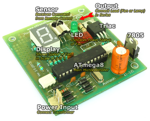 |
Fig.: Atmel AVR Based Remote Controlled Fan Regulator. |
 |
Fig.: Remote Controlled Fan Regulator Wiring Diagram. |
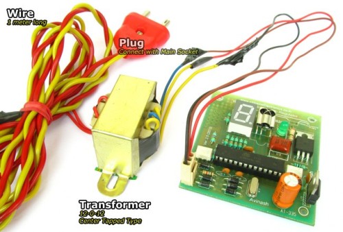 |
Fig.: Transformer with plug. |
Construction of Remote Controlled Fan Regulator.
You can make the circuit as per the schematic on any general purpose PCB. To ease your job we are giving the PCB Layouts too, so that you can make the PCB at your home using the Etching Method. You may also have the PCBs made from any fabrication house too. To further easy the job and save your money we have already made the PCBs from a good fabrication house and they are available for purchase at very low cost.
Start assembly process by first soldering the jumper1. Then you can mount the resistors. After that solder the diodes, remember to properly orient the diodes. They are polar and don’t work if installed other way round. Then solder the IC U4 and U2, this time too take care of the orientation. The small round circle on the IC package marks the PIN number 1.
 |
Fig.: Proper IC Installation. |
After that you can solder the ceramic disk capacitors, the 16MHz crystal, 7805, Triac, TSOP Sensor, Display. Finally Connect the 12-0-12 Transformer and apply power. The display should show ‘0’. Then you can press the up/down key in remote control to adjust the speed. The display should change accordingly. This ensures that the circuit is running properly.
Its time to connect a real AC load. Connect a 220V 100W incandescent lamp (NO CFL Please). As shown in the above wiring diagram. Replace the fan with bulb because its easier to test.
| WARNING !!! |
| Never Touch any part of the circuit when AC load is connected. It can give you a fatal shock !!! |
Now you can can use the remote control to increase/decrease the lamp’s brightness using the remote control. You can also switch it on and off using the ENTER key.
Troubleshooting
If the unit does not respond to the remote control signals then look for the following.
- AVR ATmega8’s Fuse BIT is programmed to
- HIGH=0xC9 LOW=0xFF
- AVR is clocked with 16MHz crystal (other value won’t work)
- Remote Control is NEC Format Only (Chinese DVD/CD player remote works good, TV Remote Generally do not work as these are RC5 coded)
- Remote Key codes has been feed to rckey.h file. Build and run this demo and press UP,DOWN and ENTER keys to get their keycode and put them in rckeys.h file. All remotes available in market has random keycode, so This part is very important. After editing the rckeys.h file the project must be Rebuild. (I hope you know what does that means).
- IR sensor is of good quality and must be labeled TSOP1738 (other values won’t work).
- If you get a KIT from us then most of the problem do not arise.
 |
Fig.: This Hobby Remote Control Works Great! |
Hobby Remote Control (NEC) is available from our online store.
Part list for Remote Controlled Fan Regulator.
Part List |
||
| 01 | 330 ohm resistor (9 Nos) | R2-R9, R14 |
| 02 | 4k7 Resistor (2 Nos) | R1,R11 |
| 03 | 1K Resistor | R12 |
| 04 | 39 ohm Resistor | R13 |
| 05 | 1K5 Resistor | R15 |
| 06 | 22pF Ceramic Disk Capacitor (2 Nos) | C1,C2 |
| 07 | 0.1uF Ceramic Disk Capacitor 250V(1 Nos) | C3 |
| 08 | 0.1uF Ceramic Disk Capacitor (2 Nos) | C5,C6 |
| 09 | 470uF 50v Electrolytic Capacitor | C4 |
| 10 | 16 MHz Crystal Half Size | X1 |
| 11 | 1N4007 Diode (6 Nos) | D2,D3,D4,D5,D6,D7 |
| 12 | LED 5mm Any Colour | D1 |
| 13 | MCT2E Opto Coupler | U4 |
| 14 | MOC3021 Opto Triac Driver | U2 |
| 15 | ATmega8-16PU General purpose 8 bit MCU | U1 |
| 16 | Triac BT136 | U3 |
| 17 | 7805 Voltage Regulator | U5 |
| 18 | Common Anode Display | DISP11 |
| 19 | TSOP1738 IR Sensor | X2 |
| 20 | 220V AC to 12-0-12 Center Tapped Transformer 500mA minimum. | |
| 21 | Hobby Remote Control (NEC) | |
Buy Remote Controlled Fan Regulator Kit.
Schematic
 |
Fig.: Schematic (Click To Enlarge/Print). |
PCB For Remote Controlled Fan Regulator.
PCBs can be purchased from PCB section of our online shop.
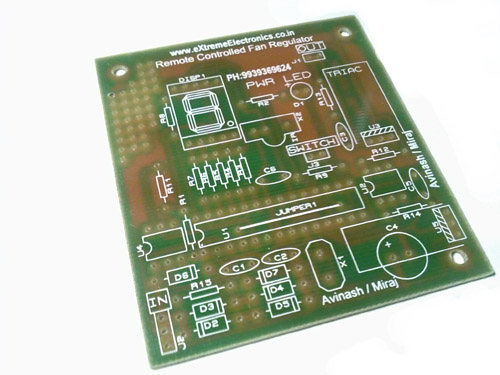 |
Fig.: Remote Controlled Fan Regulator PCB. |
Note: Other files that are part of the eXtreme NEC decoder must also be added to the project. They can be downloaded from links given below.
Check your understanding! Take a 1 minute test.
Buy Kit
Buy complete kit including PCB, Parts, Programmed MCU, Transformer and Matching IR Remote Control Unit.
Buy Remote Controlled Fan Regulator Kit.
Related Post
By
Avinash Gupta
www.AvinashGupta.com
me@avinashgupta.com
Hi Avinash! Nice project. The project file you kept for download is having some problems. When I tried to build the project, i got “no build tools defined” error. When i compiled the same files by creating a new project, there is no problem.
I build a project for controlling home appliances using DVD remote using your files with LCD support and EEPROM options. So, whenever the Main power goes off, the MCU will check the EEPROM data which has the appliances status. After seeing this project, i got an idea of integrating this fan speed control option in my project. Can i connect output to any pin say PC2 ( i bought Xboard MIni from your store, the PD5 pin is already dedicated for LCD connection). I just want to know whether the outputs you specified can be changed to other pins or not. I know we cant change the interrupt pin. I am asking about POWER LEDS and FAN OUTPUT connections.
Remote Controlled Fan Regulator using ATmega8
this is help full for us but how can i programe it for ATmega8
@Jay,
The kit which is available at your store comes with preprogrammed ATmega8.
@Arif,
Yes you can change the Triac Output pins. Simply Change the OUTPUT Section in the Initialize() Function.
And some control in the two ISRs
ISR(INT1_vect)
ISR(TIMER2_COMP_vect)’
Also Don’t forget to post your project in your blog to share with the World. And give credit to us for the Remote Libraries.
hi avinash your light dimming project is AWESOME. i trying to do same project with out IR … REMAINING CONNECTIONS ARE SAME I AM USING ATMEGA32. BY VARING ADC CHANNEL I AM DIMMING THE LIGHT CAN U SEND ME THE CODE FOR THE SAME
hureeeeeeeee i got the out put of fan dimmer
nag.praveen2007@gmail.com
I closed this circuit, but when I switch the circuit to the cabinet, I need to restart the micro-controller from the bus to work the circuit. What is the problem?
As for the AVR Studio Error Please use
Project Manager/IDE: AVR Studio 4.17 Build 666
If you post your project on your blog with pictures and code, then I will give you this PCB(Bare) for Free!!!
Sure. I will definitely post the project with Pictures and code. After all, I made that using your libraries and tutorials! I had finished the project just today. I am working on integration of speed control. I am thinking of generating pwm using atmega8 feature for speed control. Do you think the pwm logic works for speed control. I will test that tomorrow and post the results. The main reason why I thought this is to reduce the hardware and to avoid the optocouplers. But somewhere in my mind, it is saying me that a person like Avinash could have thought the same and why he implemented this the same thing with more hardware. Is it for educational purpose to cover more topics or there is a need for using the hardware?
Sorry its atmega16. not atmega8!
http://arif-ece.blogspot.com/2010/07/remote-controlled-home-appliances.html
check out the details of my project in my blog. I am working on improving the code for fan speed control using PWM. I will update it as soon as I finish doing it. Please post your comments and suggestion.
@Arifuddin,
The article you submitted is just great !
You won your PCB as I promised!
So should I send it to your registered address?
Khammam, 507001
Andhra Pradesh
Also Direct PWM Control as we use with DC Motors Cannot be used with AC Motors Such as a Fan because of following reasons
1) The PWM Must be in sync with the AC Waveform for this we use the first MCT2E Opto. By using this we fire INT1 whever the AC Wave reaches zero point.
2) Triac Can only be switched on and it remains on even if the driving voltage is removed from the Gate terminal. It can only be Turned off during the AC Zero point!
Because of these the Zero Crossing detection is necessary and simple PWM Cannot be used.
refer this too
http://www.informationjack.com/2012/02/avr-c-code-for-rms-voltage-control.html
Also the bridge rectifier section made from D2,D3,D4,D5 is NOT filtered with capacitor. If capacitor is used it will become PURE DC and we cannot detect Zero point.
Every part of the circuit is well planned and I am NOT an academic guy so I don’t add anything for mere educational purpose.
Thank you so much. My address is correct as you stated. But I also need the components that are required in the project. Please mail me the appropriate cost. I will deposit cash in your bank account.
Coming to my blog, I forgot about my blog before a long time. You initiated me for writing the article. So, credit goes to you. I did some research regarding yesterdays comment regarding PWM and found out the same. I will anyhow continue posting my projects. I read your comment in my blog regarding projects today which you sent in may 2010.
Coming to the board modification which I had done, you please check this article and give me suggestions and your feedback regarding powering the XBoardMini with USB Power supply. I think you should consider using Vcc pin in ISP connector.
http://arif-ece.blogspot.com/2010/07/modifying-avr-development-board-and.html
Thanking you,
Arifuddin Sheik
http://arif-ece.blogspot.com/2010/07/remote-controlled-home-appliances_07.html
This is the new link. I deleted the old link because the post is containing html errors. I haven’t updated the project yet.
@Arif
Your PCBs have been dispatched. You may get them by Wednesday. Please inform me when you receive them.
@Avinash
Thanks for sending me your PCB’s.
Arifuddin Sheik
Hello Avinash,
I want to build these remote controllers which can take a load of 1.5 kva. Please advice on what alteration need to be done to the circuit.
Thanks
Puneet
do you any supplier in malaysia if i would like to buy the component that used in this project?
remote control fan regulater this products is to good. I want this kit 100 pcs.
please sent price and mode of payment
@Mahendra Patel,
For Payment Option see
http://shop.extremeelectronics.co.in/shipping.php
i have this product. if u want to purchase it contact me. For more information see my website and reply me
hello avinash-
plz tell me the min ampere rating of the transformer.
that’s to be used in this project ,as in shops they ask for that too apart from voltage rating..
inform me as asap..
thanks…
Hi Avinash,
Quick question on the 220V AC to 12-0-12 Centre Tapped Transformer. Is it possible for you to direct me to a place where I could buy them online.
I’m not too sure with what I’ve found so far!
Please help,
Tandy
Hi Avinash,
Sorry for asking another question almost immediately! Basically I have a 240VAC fan to run which runs with 120W of power.
What sort of 12-0-12 Trasformer should I use?
Please help
@Tandy
I can’t get what you mean by
Hi Avinash,
Sorry I think I worded the post incorrectly.
I’m very new at this and find this project to be very interesting (a bit of a hobbyist).
I noticed that you ran a 100W bulb with your mains being at 220V AC with your transformer.
If i was trying to implement this with the fan I have what sort of transformer would you recommend.
The fan is a 120W fan(that I found lying around) and runs on 240V AC from the mains.
Please help with some knowledge thanks.
@Tandy,
12-0-12 (500ma) transformer has nothing to do with the AC load. It is just powering the logic part. So what ever AC load you use (as long as it is within the range of Triac BT136), it does not affect the selection of transformer. It is same.
Hi want source code of this dimmer, where can i get this….
Also a place to order the type of transformer that you recommend!
Thanks
Hi Avinash,
Thanks for your reply, I’m sorry I got back late with this reply because I’ve had work over the last few days and haven’t had time to play with this circuit. I’ve sort of understood the principals behind the circuit you’ve shown and understand the purpose of most parts of the circuit.
There is one thing I’m not sure of though! If you could please help that would be brilliant.
The thing I dont get is how we connect the output from the circuit board to run the lamp.
I have drawn a couple of images. One with a friend’s suggestion and one of my understanding.
Link 1
http://img201.imageshack.us/i/atmega.jpg/
Link 2
http://img14.imageshack.us/i/atmega2.jpg/
PLEASE HELP! Please tell me the mistake or any advice.
Thanks again,
Tandy
@Tandy,
This image is correct
http://img14.imageshack.us/i/atmega2.jpg/
The other is fatal! So don’t try that!
Hi Avinash,
Your absolutely awesome! Thanks man! I’m sure I’ll be posting here once again soon.
Cheers,
Tharindu
Hi Avinash,
I’ve got this finally working. It is indeed a good setup. I’ve now embarked on a project to control my water sprinkler system.
I was thinking of using a similar circuit as this one but instead of connecting the output to a 240VAC system.I thought of using a cheap step down transformer adapter as this sprinkler system runs on 24VAC.
I will then switch the sprinkler either “ON” or “OFF”.
If you can provide any thoughts that would be brilliant!
Thanks
hi Avinash,
I purchased u r fan regulator kit.and i built it.but i have some problem with it can u try to solve it…..
1.my controller portion is working properly…but i tried to connect a.c.load with ckt..and my c13 capacitor burn out.two times..i join as per u r diagram…i dont know what happen my load is continuously on and i get 13v voltage across triac.
triac is working properly or not?
plz help me to avoid this problem
thanks
Pingback: Remote Controlled AV Regulator | PyroElectro - News, Projects & Tutorials
Hi Avinash,
At first I want to thank you for such an initiative to share your knowledge with others. Your explanation ways are extremely good to describe a project clearly. According to your instruction I have made the above project on a veroboard. Everything is working correctly without AC load. But when I connect the AC load (a 40 watt bulb) at BT136 Triac’s terminal in series, the remote control does not work properly. Most of the time it was just hang. Again when the AC load is disconnected everything is working properly.
Please give me some suggestion to troubleshoot my problem.
Thanks
Hi Avinash,
I am also facing same problem as above, please give some suggestion.
Thanks,
Those who are facing problem are suggested to purchase and make using the kit.
Pingback: Electronics-Lab.com Blog » Blog Archive » Remote Controlled AV Regulator
i have build this project, everything is ok ,circuit is receiving the commands, but there is no power in the fan i have done the following observation.
1. there is 2.5v between pin 1 and 2 of opto triac(moc3021)
2. i have disconnect the optotriac pin from atmega8 and connect
it to grount but again no power to fan
plz suggest me what is the possible problem whether it is the the issue of optotriac
what is the correct no. of optotriac driver in parts list it is MOC3021. and in circuit diagram it is shown as MOC3031.
@Dinesh,
Why don’t you get a KIT from here?
http://store.extremeelectronics.co.in/Remotea-Controlled-AC-Fan-Speed-Regulator-KIT.html
DID you made it exactly (100%) as told above ??? Coz (99.99%) won’t do !!!
Hi Avinash,
Its an awesome tutorial. i have few quires presently iam designing a board where i have serial port communication. my concern is if we are taking the zero cross detection to Interrupt pin . for every 10 milli sec there will be an interrupt. so is there any case of data crash in serial port while handling interrupt and serial data at same time is there any better algorithm to implement the zero cross, Fan speed control.through Serial port..
Thank you ,
Nikhil
how the same above circuit can be used to control the speed of coolers?
please help & let me know
I purchased a Kit from your site. Firstly the kit was missing two resistors and contained resistors of wrong value. I emailed this problem to you with the pictures. Subsequently I purchased the resistors from local market and built the kit. After building the kit the display is working and responding to the remote control. Also, by pressing enter key the power LED toggles between on/off.
But when I connected a 60W incandescent lamp the lamp always remains at full brightness, it doesn’t dims as per the remote control output. It also doesn’t turns on/off while pressing enter key on remote.
I’ve mailed quite a number of times regarding this and you didn’t help.
I find this type of attitude totally unacceptable. First you sent me kit with missing part and wrong parts. When contacted you asked me to return the kit at my own cost. The cost of the parts is way cheaper than the courier charge. As a customer friendly approach you should have sent me a new kit and arrange to pickup the same.
Also, after several request to look into problem of non-working kit you didn’t help at all.
So, look into the matter immediately and tell me how to get the kit working.
Hi Avinash
I got ur pcb via dtdc
bt i have some prob in remote controlled fan regulator
R13-39 ohm or 39k which, one coz i used 39 ohm and it burned plz help me
can i used atmega 8L-8pu
i want also used on\off other room goods. can help me ?
very nice project
i want used without remote
i want add 3 SWITCH 1-up 2-DOWN 3-on /off
what Change in code ?
hello avinash … i have a few doubts …
when using a compiler, most of the initialization code is completed by itself .. like setting a bit for interrupts, adc and much more …
due to this all i know is how to write code with pre-implemented compiler initialization. but you write the whole code and it gets difficult for me to get about such codes ..
can u point me to the right direction in order to write the complete code by myself, without the use of compiler .like with the help of notepad .. from head to toe …
lol . i am not askin for a complete tut. but just a push in the right direction…
can u explain working of this circuit…??? please
Remote Controlled AC Fan Speed Regulator KIT.i want this kit can i get this kit .in your website it shows out of stoke……..piz send me reply…….
Hi, I made very similar circuit, and it works fine with the incandescent lamp, however when I connect my fan heater(heating is turned off) – works only fan, it doesn’t change the speed. If the speed is set to 50% it barely rotates. The same is with all speeds except 100%.
Any ideas why??
hi avinash, i want to implemnt ur projct for contrlng the speed of my ceilng fan but recently i have made one more circuit to switch tubelight of my room on and off through remote and in that circuit also, i have used TSOP 1738 and in the same room i want to fix ur circuit, so i have a doubt that whnevr i’ll press any key on remote then it will effct both the circuits i.e. if i want to switch off my light only without effecting the fan then it will b impossbl to do.
good site
hi avinash , pls reply on my cmnt i need ur help….
dear sir
I just want to controll the speed of submersible water pump, 230 v AC. for which i have used AVR 32 L Mc, and 3011 optocoupler, and BTA 12 traic,
Bt when i switched it ON, the speed of the motor is not controlled, it gts switched ON, and then no response, i have to switch it OFF by manually switching the AC mains supply.
Need your guidance
Regards
Vishal
Hello Sir , We Want To AVR Remote Controller Fan Regulator PCB’S Cost & What’s Process For Collect Your PCB.
hi
can someone tell me what is sil-100-02 in the circuit diagram?
It’a a conector with 2 trails. It can be any kind you want.
Can you please help me out with my problem. I use ATMEGA 32, all the other pieces are the same. When i remove the wire from INT1 the dim works but it’s not in phase. What can i change to make things work.
hello avinash
can i use atmega8-8pu instead of atmega-16pu because 16pu is not available in my city. if it is possible than please tell me after anything change can i use atmega8-8pu for above project…??
How much it cost in rupees?
nice project guys.
But I really want to do this project and intend to have the tutorial. SO ,can u help me out.
Nice project but I think you can reduce the build cost by opting for an alternative for the AC 50/60Hz zero cross detecting opto (MCT2E). The AVR182 appnote has a rather simple way of addressing this by directly feeding the AC mains output to one of the MCU’s external interrupt pins with a series 1M ohm resistor in parallel.
Made a mistake in the previous post. The 1M ohm resistor is in series and not in parallel.
why wont other values of crystal than 16 Mhz work? cant we use 8 Mhz ??
because while writting the program we need to do some calculations. And we assume at what rate the CPU is running. So during all those assumptions we used 16MHz. Thats why if you run at other frequency it wont work. Anyone work
thank you sir! 🙂
hi avinash sir..
i buy pcb for fan regulator from your online shop and assamble it.
i program microcontroller which you given above with fuse bits.
when i run it i seen that there is only number is change from 0-9. but even status led not glow.and also there is no change in lamp intensity.
can you suggest sir there is whats going on.
does i need to take any other precausion…??
plz reply sir..
Hello,
I have a problem with interrupts in my project. I was using the same rule as in here and I’ve initialized interrupts like below:
MCUCR=0x00; //(low level of INT1 initializes interrupts)
GICR|=_BV(7); //INT1 set to one
I have also used to function sei(); and in the line with command:
ISR(INT1_vect)
there were two errors:
264: error: static declaration of ‘__vector_2’ follows non-static declaration
264: error: previous declaration of ‘__vector_2’ was here
I can’t figure out what’s wrong. I use AVRstudio with AVRdude.
@Jacob,
First off all tell me which MCU is being used ?
And the version of AVR Studio
Also upload full AVR Studio Project in the forum so that we can examine.
http://forum.extremeelectronics.co.in/
hi avinash i tried to make your project but i interfaced it with lcd and want to use sony remote which works on sirc protocol can you help me out in decoding n coding part of my project as i am new to it so i don’t have any idea of how to use winavr or any startup guide to understand how to write codes for avr controller.iy would be indeed very kind of you if you can help me i would able to learn a lot from you.just i want to get my programming base clear.
@Meet!
You guys drive me crazy! Asking such f***ing questions! Why would in the world I will spend any time for your project ! I already have important people in my life to take care of ! And I am already too busy to get time for them.
sir Avinash, i want to know, what kind of software you used to draw that schematic. i’m newbie and uses software ISIS but can’t find component tsop1738 and moc3031. hope tou can help me. thank you very much.
@Sao,
So make them !
Hi Avinash, Can I ask you a question, for transformator, how much ampere do you use?
Hello,
You know that your software code has a bug and it will never work without modification? I think you know very well. 🙂
Mr. Avinash, Can you please upload the simulation(Proteus ISIS) file of the circuit?
Hi Avinash, can i ask you onbe more question, what is the function of J3 in your schematic?
bit programing for 2 fan regulator and 4 light
dear sir . if possible pl provide here 16f676 based code.
@Sahu, Sorry NOT available.
any other PIC MCU ?
hellow sir… can u pls give the block diagram and circuit explanation of this circuit
@Athira,
NO !
Hi Avinash,
I recently purchased the RC Fan Regulator Kit from your website and assembled the same as per the instructions keeping all the polarities and tips in mind.
Now when I switched on the complete circuit with 12V transformer the display is showing zero, but the circuit is not responding to remote (received in kit).
Now is this MCU programmed and sent with matching IR sensor & remote as mentioned on your website.
Or it needs to be programmed as suggested in this article.
see the instructions written on the box what to do when you ran into problems.
Hey Avinash,
In the circuit you have used the opto coupler as a frequency sensor but I did not see it being utilized in your code. Could you please share the requirement for this or could you please point out the code that uses this.
Regards,
Kashyap
@Kash
The MCT2E Opto Coupler is NOT used as a frequency sensor. But as an input to detect 0 crossing of the AC Waveform. The output PWM needs to be in sync with the AC wave form. If Output PWM is NOT in sync with AC wave form we cannot predict the power delivered in that cycle.
INT1 handler make use of this zero crossing detector.
It switches off the trick on every cycle of AC waveform as it detects 0 crossing
and sets an alarm which switches on the triac after a preset interval. The longer this interval the lower the power delivered to the load in that cycle. This interval depends on the current speed of regulator.
Hi Avinash,
I have a simple concern. Will this work with UPS both with square and sine waveforms.
Hey Avinash,
Please give me the block diagram…
@Souvik, If I had the block diagram I would have put it here only!
Hi avinash,
i am trying to make to control fan and light speed via RF modules.
I need your assistance on it.
Plesae help me
Dear Avinash,
Can we use a coin cell(CR2032) instead of using 12-0-12 transformer and relay for making/braking contact instead of triac?
Please,reply.
will this work on 220v / 60hz ac mains?
Hey Avinash!
tell me the way to design this remote controller with 4 fan controller i.e for 4 channel
Hi Avinash,
Great implementation, it helped a lot in some of other projects.
Just a thought, why you have used an external crystal with 16Mhz of frequency. I think the internal oscillator @ 1Mhz will work (even with 10% tolerance).
Thanks
Neelesh
Hello sir,
I was success build the remote test to decode NEC with some modification.. I just to tell you that your code have a little wrong..
In “remote.c” you wrote TCNT0=0;
it should be TCNT1=0;
Thank You
Thank you Avinash
I request you to please write an tutorial about zero crossing detector
May be all are facing problems due to it
May be they are not using transformer. May be they are using regulated supply directly
And if tutorial already exists at extreme elect somebody let me know the link
I just want to know zero crossing detect more closely
What I understand reading previous comments is that
Triac can be switched off at close to low ac cycal
And also if we on and off zero crossing triger triac input to low or off when ac cycal is low by referring the ac at INT1
which results in less chances of spikes.
If I am correct please let me know
Either I am or not correct
Heartly request you to write the tutorial on zero crossing detection
Hey!
Visiting your website after a long time! 😀
Just found a little mistake here in your disclaimer…
You state
“WARNING !!!
Never Touch any part of the circuit when AC load is connected. It can give you a fetal shock !!!”
You might wanna change that ‘fetal’ to ‘fatal’ or ‘lethal’… 😛
I’m sure no one wants to get a ‘fetal shock’ either! 😀
Regards
Pranav
@Pranav
Thank you 🙂
can it be made using arduino uno atmega328??? if yes, could u plz tel me what changes have to be made??
Can any one tell me how can i store the present status of the speed into EEPROM so that it can resume after power failure.
@hemghosh04 pay us Rs. 1000 to get this done!
HI. It is such a nice project. i request you to make me understand that how you are firing the triac?
Very nice project!
But what if I want to increase the number of fans, say controlling speed of two fans instead of one.
What are your thoughts on this.
Waiting for reply.
Hi Avinash, is this “remote controlled fan regulator” store status in EEPROM(or Resume fan on previous set speed when power resume), Thanks
@Tariq
Yes I have improved the firmware with that functionality, but is not shared here. I use that for my personal use.
is Your EEPROM status Saving Remote Fan regulator Project available for sale ?, if yes please tell me the Cost,
@Tariq
Yes.
http://shop.extremeelectronics.co.in/product_info.php?cPath=53&products_id=237
Dear friend,
please can you give me the circuit diagram for the same project using PWM,
i will upload the code using arduino.
thanks in advance.
Hi,
i want to know about the code of this project.
avinash your code dose not compiling in my arduino platform which is 1.0.5-r2
please provide me some solution for making this type of project.
omprakash sahu,
This code is NOT for arduino!
If you want compilation steps then we can send you.
Hi,
I want to know the power circuit diagram, with triac and/or Diac no.s and optoisolators no. and how they are interfaced with AVR PWM
Do you have a design for this board with SMD components to make this very small board.
@Rahul,
Nope!
Do you have a similar circiut which I can operate with raspberry pi. I actually want to control AC fan speed using raspberry pi.
Hello Avinash,
Your project works really great. I have implemented part of it in my project. Works really good.
I found few difficulties. Please help me to understand.
So my project is about home automation. I am using ATmega8 to controller fan tube light bulb & TV using Bluetooth.
1] I want to control 2 fans but i am finding it difficult… I have used Timer1 in CTC mode and used OCIE1A and OCIE1B to control different speed.. but its not working
2] Also when i switch on or switch off tube light my micro controller behaves randomly.. it switch offs all loads or turns on off load..
i am not getting any solution for this i tried it with BT136 and with electromagentic Realy too..
can u please suggest me somthing?? where its going exactly worng..
@Vaibhav, Thank you. I am glad you found them usefull.
Hello Avinash,
Could you please help me to find out solution to my mentioned problems??
@Avinsah
Could you please help me to find out solution to my mentioned problems??
My R C Fan regulator worked first time no glitches!
It has been tested with an incandescent lamp, dimming is working.
how to download this project files……………………..
@Mahendra,
Please purchase the KIT from our store and we will provide the project files in an optical disk. Thank you.
Avinash,
Thanks for your project. It’s great for learning.
I want to add two tactile switches to speedup/down the fan speed. I already talked to your personnel, they asked to deposite Rs.1000 for some upgreadation. I am agreed & ready to send the money.
Pl. tell me ( after deposition of money)
1) where those tactile switches are to connect in the circuit and modified code for ATMEGA8.
2) If I want to powerup the circuit by capacitor instead of bulkey transformer is it possible ?
3) how should I pay you Rs.1000 ?
Thanks … looking for your reply.
SOM NATH ROY
Email : somnathkolkata@hotmail.com
Ph.: 09433429107
Hii Avinash i like your project very well.
I am ready to purchase this kit.
I want power button of the remote for on/off the load.
Isn’t it possible.I want control my hometheater (on/off) remotely with fan too.
i want your help help me my email shariqrajput9@gmail.com and m.n +919761197690
hi avinash… i want to purchase this project…have a problem ! my country is Bangladesh.. city is dhaka..can i get this here ?
@Robin,
Sorry, not possible to ship to BD.
hi avinash,i mailed regarding my project can you please reply me. i called you i dont know my voice is not hearing for you i thing.i am calling you from germany.that is why my number is like that.please reply me i am in urgent about project.
Very impressive project. Any body can explain or modify to use as rfid based system. For this system you must operate remote by point the remote. I want to operate it from any location with in the rfid range.
Hi,
I interested in your project very much. How I can buy PCB?. How much shipping to Thailand?
Regards,
xxoops
i am begineer in microcontroller. can you give me the program for this project. this is helpful to me to complete the project.thak you
I am fresher in micro controller .i like to your circuit for my project.plz give me the program ,which will be help for me.
Send me its program and PCB circuit diagram in my mail all product as mentions above i buy it
Send me AVR MCU program and circuit diagram
I would like to use the circuit to implement a temperature controlled fan controller for an exhaust fan in my garage. The fan will be a 110V model. Am I correct in assuming that all I’ll have to do is change R12 to 470?? Should I adjust R13 and/or C3 as well?
Also, do you have any experience with how much power the BT136 can switch before it needs better cooling?
I am pretty sure I can figure out how to hook up and program and LM35 temperature sensor. But if the source code for the dimmer circuit is available, that would safe me some efforts and get me started easier.
Hello Avinash
i make this project but i faced a little problem in my project the zero crossing detector is not working ? & remaining part is working well as 7 segment display shows the speed & o/p led as well.
i cross check the circuit & the Code too …..
SO CAN YOU HELP ME ?………….
where i am going wrong ?
Thanks
Fully assembled and tested project is available for sale in our store. Please purchase from there.
Hey Avinash,
Can I have your project’s programming code please?
Hello Avinash, i bought the fan speed control using infra red kit few months ago. I know the microcontroller is preprogrammed but can you please send me the codes ?
I am trying to build the project on my own referring your design but need the coding to get it work. Please share the programmings . Thanks
Hi avinash… I have joined all the components according to the circuit but when I plug in the power I cant see any light glowing in display or in led… nothing is happening
@Hari,
That’s why I have made a kit for sale so that I don’t have to personally see each users prototype and help.
Dear avinash can you please share the code to (shinaskhan088@gmail.com). Iif you help i want to make one for myself ???? . Please reply I’m new in arduino. Thanks
sir
can u send me a code for ATMEGA8 microcontroller plz
Hi,
If i have to use arduino ready made board for AC fan speed regulation what care i have to take.
or simply i can use circuit after optocoupler
Thanks,
Ankush
Hi Avinash
Does it make humming noise at low speeds?
Thank you
No it does NOT makes any humming noise.
Dear,
Thank”s
Hi
Where can i get the code for the ATMEGA?
Regards
Hi Matthew Ogilvie,
I have recompiled EE’s code, I will need permission from Avinash to do so.
Hello Mr Avinash,
I had purchased the kit for this regulator from you, it is working good.
I thought Id make another one and program the atmega 8 myself from the code included in the CDs included in my orders.
While I am compiling the code I am getting compile errors.
Is the code and the library files in the CD the one you use to compile your AVRs included in the kit.
Regards.
Karanbir
Dear Avinash,
Can I change some of your code in the fan.c file.
All the info at the top of the fill will remain. I was just thinking of recompiling the code on another platform.
Regards.
Karanbir
Hello Avinash,
I thought of adding some change to your project which is working fine.
I want to store the last speed value and on / off position in the internal EEPROM, so that during a power off condition it starts up at the same value.
I have connected a 10 pin box header as an ISP on the main board so that i can reprogram another ATMEGA 8 MCU.
I will post the results once I am done.