Many application requires large number of keys connected to a computing system. Example includes a PC keyboard, Cell Phone keypad and Calculators. If we connect a single key to MCU, we just connect it directly to i/o line. But we cannot connect, say 10 or 100 keys directly MCUs i/o. Because :-
- It will eat up precious i/o line.
- MCU to Keypad interface will contain lots of wires.
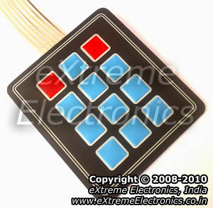 |
Buy Matrix Keypad |
We want to avoid all these troubles so we use some clever technique. The technique is called multiplexed matrix keypad. In this technique keys are connected in a matrix (row/column) style as shown below.
 |
Matrix Keypad Basic Connection |
The rows R0 to R3 are connected to Input lines of Microcontroller. The i/o pins where they are connected are made Input. This is done by setting the proper DDR Register in AVR and TRIS Register in PIC. The column C0 to C3 are also connected to MCUs i/o line. These are kept at High Impedance State (AKA input), in high z state (z= impedance) state these pins are neither HIGH or LOW they are in TRISTATE. And in their PORT value we set them all as low, so as soon as we change their DDR bit to 1 they become output with value LOW.
One by One we make each Column LOW (from high Z state) and read state of R0 to R3.
 |
Column 0 Selected |
As you can see in the image above C0 is made LOW while all other Columns are in HIGH Z State. We can read the Value of R0 to R3 to get their pressed status. If they are high the button is NOT pressed. As we have enabled internal pullups on them, these pullups keep their value high when they are floating (that means NOT connected to anything). But when a key is pressed it is connected to LOW line from the column thus making it LOW.
After that we make the C0 High Z again and make C1 LOW. And read R0 to R3 again. This gives us status of the second column of keys. Similarly we scan all columns.
 |
Column 1 Selected |
How to Do it All with AVRs
Each i/o port in AVR has three related registers PORTx, DDRx and PINx. For example port A has
- PORTA Port Driver – when any bit is set to 1 it appears as HIGH i.e. 5v . But this is the case only if that bit is OUTPUT. If it is input, setting any bit to 1 enables the internal pullup on that bit.
- DDRA DATA DIRECTION REGISTER – Make any pin on than port as IN or OUT. When bit is 1 it represents Output. When bit is 0 it represents Input. Input state is also called tristate or high Z state.
- PINA – Read it to get the level (HIGH or LOW) at the actual i/o pin. It is read when the pin is made input.
So now you know
- How to make any i/o line Input(high Z) or Output.
- How to enable internal pullup register on input lines.
- How to read value that is present on input lines.
Please see the following tutorial for more clarification.
Why we make other Columns High Impedance while one column is made LOW?
Lets say we selected column number C0, so we make it LOW(i.e. GND or logic 0), in the same time we make all other columns high impedance (i.e. input). If we don’t make other lines high impedance (tristate or Input) they are in output mode. And in output mode they must be either LOW(GND or logic 0) or HIGH (5v or logic 1). We can’t make other lines LOW as we can select only one line at a time and C0 is already low as per assumption. So the only other possible state is all other columns are HIGH. This is shown in figure below. Red colour on column indicate high state while green is for low state.
 |
Wrong Way! |
Suppose at that time the user presses KEY0 and KEY1 simultaneously as shown below.
 |
Short Circuit ! |
As you can see clearly that it create a short between C0 (GND) and C1 (5v), this will burn out the buffer of the MCU immediately!
 |
Short! |
That’s why all other columns are kept at tristate(neither LOW nor HIGH) but very high input impedance that prevent either source or sink of current from them. So if we kept C1 at high impedance state it wont allow current to flow to GND on C0.
avr-gcc C code for 4×3 matrix keypad
1     /******************************************************************************
2
3     Program to learn the use of Multiplexed 4x3 keypad with AVR Microcontroller.
4
5     Specific Skills Required
6        >> AVR GPIO details.(http://bit.ly/aq3ouw)
7        >> LCD Library.(http://bit.ly/agVUVc)
8        >> Operations on bits using C.(http://bit.ly/aFqg5n)
9
10
11    General Skills Required
12       >> AVR Studio Setup and use. (http://bit.ly/aZ43SZ)
13       >> avr-gcc setup and use.
14
15
16    Hardware
17    --------
18    ATmega32 @ 16MHz external crystal.
19    Fuse Byte setting HIGH = C9 and LOW = FF (MOST IMP.)
20
21
22    LCD   <->   AVR Connection
23
24       VSS ->GND
25       VDD ->+5V
26       VEE -> CENTER PIN OF 10K POT (OTHER TWO PIN OF POT TO +5V AND GND)
27             ADJ. THE POT UNTIL YOU HAVE A CLEAR TEXT DISPLAY.
28
29       RS -> PD3
30       RW -> PD6
31       E  -> PB4
32
33       DB0 -> N/C
34       DB1 -> N/C
35       DB2 -> N/C
36       DB3 -> N/C
37
38       DB4 -> PB0
39       DB5 -> PB1
40       DB6 -> PB2
41       DB7 -> PB3
42
43       LED+ ->+5V (VIA 100 OHM RES)
44       LED- ->GND
45
46    KEYPAD
47
48       COL1 ->  PA6
49       COL2 ->  PA5
50       COL3 ->  PA4
51
52       ROW1 ->  PA3
53       ROW2 -> PA2
54       ROW3 ->  PA1
55       ROW4 -> PA0
56
57                                NOTICE
58                               --------
59    NO PART OF THIS WORK CAN BE COPIED, DISTRIBUTED OR PUBLISHED WITHOUT A
60    WRITTEN PERMISSION FROM EXTREME ELECTRONICS INDIA. THE LIBRARY, NOR ANY PART
61    OF IT CAN BE USED IN COMMERCIAL APPLICATIONS. IT IS INTENDED TO BE USED FOR
62    HOBBY, LEARNING AND EDUCATIONAL PURPOSE ONLY. IF YOU WANT TO USE THEM IN
63    COMMERCIAL APPLICATION PLEASE WRITE TO THE AUTHOR.
64
65
66    WRITTEN BY:
67    AVINASH GUPTA
68    me@avinashgupta.com
69
70
71
72    ******************************************************************************/
73
74    #include <avr/io.h>
75    #include <util/delay.h>
76
77    #include "lcd.h"
78    #include "myutils.h"
79
80    #define KEYPAD A  //KEYPAD IS ATTACHED ON PORTA
81
82    //Don't Touch the lines below
83    //*******************************
84    #define KEYPAD_PORT PORT(KEYPAD)
85    #define KEYPAD_DDR   DDR(KEYPAD)
86    #define KEYPAD_PIN   PIN(KEYPAD)
87    //*******************************
88
89
90    /*******************************************
91
92    Function return the keycode of keypressed
93    on the Keypad. Keys are numbered as follows
94
95    [00] [01] [02]
96    [03] [04] [05]
97    [06] [07] [08]
98    [09] [10] [11]
99
100   Arguments:
101      None
102
103   Return:
104      Any number between 0-11 depending on
105      keypressed.
106
107      255 (hex 0xFF) if NO keypressed.
108
109   Precondition:
110      None. Can be called without any setup.
111
112   *******************************************/
113   uint8_t GetKeyPressed()
114   {
115      uint8_t r,c;
116
117      KEYPAD_PORT|= 0X0F;
118
119      for(c=0;c<3;c++)
120      {
121         KEYPAD_DDR&=~(0X7F);
122
123         KEYPAD_DDR|=(0X40>>c);
124         for(r=0;r<4;r++)
125         {
126            if(!(KEYPAD_PIN & (0X08>>r)))
127            {
128               return (r*3+c);
129            }
130         }
131      }
132
133      return 0XFF;//Indicate No key pressed
134   }
135
136
137   void main()
138   {
139      //Wait for LCD To Start
140      _delay_loop_2(0);
141
142      //Now initialize the module
143      LCDInit(LS_NONE);
144
145      uint8_t key;
146
147      while(1)
148      {
149         key=GetKeyPressed(); //Get the keycode of pressed key
150
151         LCDWriteIntXY(0,0,key,3);  //Print it at location 0,0 on LCD.
152      }
153
154   }
The above code make use of the LCD Library. You can get more information on LCD Library here :-
Hardware for 4×3 Matrix Keypad and AVR interface.
The test circuit will be built around ATmega32 microcontroller. The output device will be a 16×2 lcd module. So we set up a basic ATmega32 circuit. The circuit will have the following :-
- ATmega32 MCU
- 16MHz Crystal
- Reset Circuit.
- 5v Power Supply Circuit.
- ISP (For programming)
- LCD Module.
- LCD Module Contrast adjust pot.
 |
ATmega32 + LCD + Keypad Interface. |
We have built the above circuit on a Low Cost AVR Development Board, but it does not has inbuilt LCD Module connector so you need to solder it yourself at the free area (and also do the wiring).
Compile the above program using AVR Studio (compiler is avr-gcc). And finally burn the program using any ISP Programmer to the ATmega32. The fuse bits must be set as following to enable external crystal as clock source.
- High Fuse = C9 (hex value)
- Low fuse =FF (hex value)
After burning the HEX file to MCU, finally you are ready to power up the setup. When powered on, the LCD Screen Should show you the keycode of the key pressed on the keypad. This complete our test.
Troubleshooting
- NO Display on LCD
- Make sure AVR Studio Project is set up for clock frequency of 16MHz (16000000Hz)
- Adjust the Contrast Adj Pot.
- Press reset few times.
- Power On/Off few times.
- Connect the LCD only as shown on schematic above.
- No response to key press.
- Check that keypad is connected on PORTA only.
- If you want to attach keypad on different port, change the line 80 on source code (keypad.c)
#define KEYPAD A
        //KEYPAD IS ATTACHED ON PORTA
- Compiler Errors
- Many people these days has jumped to embedded programming without a solid concept of computer science and programming. They don’t know the basics of compiler and lack experience. To learn basic of compilers and their working PC/MAC/Linux( I mean a desktop or laptop) are great platform. But embedded system is not good for learning about compilers and programming basics. It is for those who already have these skills and just want to apply it.
- Make sure all files belonging to the LCD Library are "added" to the "Project".
- avr-gcc is installed. (The Windows Binary Distribution is called WinAVR)
- The AVR Studio project Type is AVR GCC.
- Basics of Installing and using AVR Studio with avr-gcc is described in this tutorial
- How to add files to project is described in this tutorial.
- General Tips for newbies
- Use ready made development boards and programmers.
- Try to follow the AVR Tutorial Series from the very beginning. (Remember the list spans four pages, page 1 is most recent addition thus most advance)
Video For 4×3 Keypad Interfacing.
User Videos
By BrendinI really appreciate Brendin’s approach on getting his problem solved and successfully porting the demo to ATmega48. What I recommend the users is to get your basics strong. You need full understanding of C language concept and the full details of the device you are programming, this will save you lots of time. So please go and read the good book on C and the datasheet of AVRs before you dive in! – Avinash
Downloads
- Atmel Studio 6 Project For 4×3 Keypad Interface.
- Proteus Simulation
- HEX Code ready to burn to ATmega32
Help Us!
We try to publish beginner friendly tutorials for latest subjects in embedded system as fast as we can. If you like these tutorials and they have helped you solve problems, please help us in return. You can donate any amount as you like securely using a Credit or Debit Card or Paypal.
We would be very thankful for your kind help.
By
Avinash Gupta
Facebook,
Follow on Twitter.
www.AvinashGupta.com
me@avinashgupta.com
Hi Avinash,
great tutorial again, but you diddnt add the .c file as a part of the download. It would have helped to find out how your program actually works!!
Regards,
Mayukh.
All the files are provided at the end! I think you should be more careful before complaining. This confuses the other readers
Hi Avinash,
the objective was to remove my confusion!! When i checked ur site, i didd’nt see the first link under downloads (which does not necessarily mean it was not there). I wanted to compare my code (for a 4×4 kpad) with yours (keeping yours as referance ) as my approach for scanning the keys was somewhat different, making use of one loop and without the shifting.
Regards,
Mayukh.
Great tutorial. Could this be adapted for my atmega48 mcu? I was able to get the LCD tutorial to compile for the 48 but this one won’t build.
Build started 19.10.2010 at 17:05:01
avr-gcc -mmcu=atmega48 -Wall -gdwarf-2 -std=gnu99 -DF_CPU=16000000UL -O2 -funsigned-char -funsigned-bitfields -fpack-struct -fshort-enums -MD -MP -MT Keypad.o -MF dep/Keypad.o.d -c ../Keypad.c
../Keypad.c: In function ‘GetKeyPressed’:
../Keypad.c:117: error: ‘PORTA’ undeclared (first use in this function)
../Keypad.c:117: error: (Each undeclared identifier is reported only once
../Keypad.c:117: error: for each function it appears in.)
../Keypad.c:121: error: ‘DDRA’ undeclared (first use in this function)
../Keypad.c:126: error: ‘PINA’ undeclared (first use in this function)
../Keypad.c: At top level:
../Keypad.c:137: warning: return type of ‘main’ is not ‘int’
make: *** [Keypad.o] Error 1
Build failed with 5 errors and 1 warnings…
Sorry…but I got it to compile…I just needed to change to Keypad.c to use PORT B.
#define KEYPAD B //KEYPAD IS ATTACHED ON PORTA
I will try and breadboard it and see if it works.
I got it working on the atmega48. I needed to also set the reset pin disable to set PC6 as I/O (this unfortunately means I can no longer program with the ISP programmer). The code works for every button except 2 and 3 (using a 4×3 keypad 2 and 3 are equivalent to 2nd and 3rd button on the top row in this tutorial). When I hold down the 2 button the LCD flashes between 0 and 1 very fast. When I hold down 3 button the same thing happens but flashes between 0 and 2. All the other buttons work properly
I am not using an external clock. Fuse settings are Low=E2 High=5F and Extended=FF
What would cause this?
thanks,
Brendin
I changed some things around and got it working. I put the lcd data on port C and the keypad on port B. Now I don’t have to worry about setting port c6 as an input and disabling reset. All of the keys output as expected. Here is a youtube link.
http://www.youtube.com/watch?v=7buBfN0kn04
Changes I made
lcd.h
/************************************************
LCD CONNECTIONS
*************************************************/
#define LCD_DATA C //Port PB0 TO PB3 are connected to D4-D7
#define LCD_E C //Enable/strobe signal
#define LCD_E_POS PC4 // PB4 Position of enable in above port
Keypad.c
#define KEYPAD B //KEYPAD IS ATTACHED ON PORTA
@Brendin
Congratulation on your success in porting the code to ATmega48!
hi avinash..!!nice tutorial again..very helpful to me..
thank you..!
Pingback: I-Deliver Robot « Mohamed sherief's Blog
Pingback: keypad interfacing....................................... .........
Pingback: AVR Project – ATmega8 Based Smart Code Lock | eXtreme Electronics
Hi Avinash
I have interfaced a 4×4 keypad using atmega32 and I face similar problems as Brendin. I mean, whenever I press the 2nd, 3rd and 4th keys, the display flashes between 0 and 1, 0 and 2, 0 and 3 respectively. Unlike his case, the problem did not solve by changing the ports…
@maxmiaggi
Bring out your oscilloscope, logic analyzer and in circuit emulator and fire your debugger !!!!!
Coz I have got no ESP like spiderman.
Hi Avinash
Great Work….keep going. please give complete tutorial how to interface LCD with ATmega32 microcontroller with code…thank u for your time
@ Maruf ,
U have to climb b4 u reach the hilltop, so b4 commentin plz check the complete archive of this website…. Its all given….
LCD module has been explained quite well.
@ Avinash ….
Gr8 work dude . Can u post an article on how to hack/mod an RF toy car and put it to use instead of buying an new RF module .
Lol , only for those who already have a toy car at hom. !
@Sinet,
Its better to use ready made RF Module because.
1)Better quality.
2)Optimized for data transfer.
3)Cheap
Hi, Google “hack toy car to make wireless robot” the first link that come should be what you are looking for
@Avinash
I understand ur point of view …. but if a person has already got a toy car , all opened up then why hesitate in experimenting. If u have time can u atleast tell how can i connect an AtmegaXX to the RF toy car circuit … Correct me if i am wrong anywhere ….
Another question is how can i increase aerial data transfer range if i bought a RF module, for, currently i noe its limited to a modest span of some feet. Cuz elec.mag waves can propagate long distances.
Is it achieved with the aid of repeaters (Power Boosting ). And if i dont have repeaters(non commercial experimentation) then how can i increase range of RF module by increasing its Power i/p .
@Sinet Rags,
Their are various RF Toy car in the market. Each one has a module made specially for that car.
Even the cheapest RF module works great at-least giving 50 feet range in full urban environment.
If your is giving only few feets then their may be series design fault in your designs.
@ Avinash …
any coding tricks in order to reduce the size of this code ???
In the “p” section a user can delete a written character .
Feedback required / THANKS !
@ Avinash . dude remove my code . it isnt full . if u dont mind i can post the complete code ! its ready . tested . woking
Hi Avinash,
As Brendin said that to use PC6 as input we have to disable RESET. Then,
1. How can we program AVR in such cases?
2. Whenever, I use PC6 as output, on pressing the
RESET switch, how does RESET gets activated,or,
what happens internally??? Does it generate some
kind of interrpt???
3. Somedays ago in a wireless robo-boat championship I
saw that none of the boats were working.
All the boats had RF modules attached all of the
same frequency, but DIFFERENT ADDRESS BITS set in
the Rx and Tx. Can you explain? Is it because all
of them were trying to work at the same frequency?
If yes, Why are address bits provided in Rx and Tx
modules using a DIP switch……..
Thank You in advance
@Avinash
Plz guide me for how to interface 4*4 touch keypad to atmega 32.
and if u have any readymade module for the same purpose then let me know.
where is the pdf version for this ?
@avinash can u tell me how to use this code for 4X4 keypad ?
i am a beginner kindly help me !!
The program works no doubt in that.
But, you might encounter some key malfunctioning problems if you don’t add a 1ms or 2ms delay before reading the inputs especially when you are running at 16MHz.
It’s always advisable to add a 1ms or 2ms delay after you change the state of the port pins before reading.
If anybody encounters a problem with interfacing with the above program, kindly add ‘_delay_ms(1);’ in line 122 and between lines 123 and 124. If problem persists increase the delay to 2ms.
Thank you so much for this comment. I amended his code for my own 4×4 keypad and spent hours wondering why my first row wasn’t quite working until I read your comment and added a few asm nop’s in there, thank you so much. Works a charm.
@Max
Thanks for feedback !
Can I get the pdf version of this article ?
Please give me matrix keypad interface code for PIC 16f84 microconttrolar in C language. plzzzzzzzzzzzzz help me.
@Emran this is advance of C code.You can change for different micro controller with vary few changes.No one can write code for every micro controller and compiler.If you know about the 16f84 then change it according to your requirement.other wise jaisa bana hai bana do jayada tension kyun lena.
Can I have the pdf fille of this ?
Thank you
What changes should i make if i want to read multiple keys at same time. more than one keys will be pressed at a same time, and i want to read them. Thanks
Pingback: 3×4 Keypad | Ketturi electronics
use diode in reverse to the output pin and pull up all port…that’s it .. simple
Mr. Avinash,
Thank you very much for such an elaborate tutorial.
I was trying to interface a 4 x 4 key pad with MSP430x, after few hick-ups in the beginning I was able to debug the problems and resolve them.
Once again thank you very much for your article.
regards,
s-ä-g-ä-r
@Sagar,
Welcome.
thank for your code.
but in line 28 have a problem and must be 3*r-c to get right number
Dear Avinash How to convert this program like mobile key pad say 1 key have 3 charters to display.kindly help me out please
Pingback: DS1307 I2C RTCC Interface using SoftI2C lib - eXtreme Electronics
hi Avinash sir, i tried to interface 4*4 keypad with atmega16 but it displays numbers more then one time. e.g if i press 1 it displays 111111.
may i know how to use keypad by using assembly language……(i mean code in assembly laguage for keypad)
your tutorials are very helpful….but the main problem is in assigning keys to a keyboard….we want to do a mini calculator project…plz help in coding using atmega32 in c
I need to interface both the keypad and the Graphical LCD (ks0108 controller) with ATMEGA 16 or 32. can you please be helpful?
Hi hi Avinash,
Great tutorial. Is it possible to use another value of XTAL or internal XTAL?
Thank
Hi Avinash,
Thank you for this great tutorial. I need your help. I have built the the 4×3 Matrix Keypad Interface – AVR Tutorial using Atmega162.
I did not change anything only the microcontroller. I kept the c code as it is. I built it exactly as yours but i am not getting the digit in the LCD as yours. I am getting random keys.
My question is the keypad has got 7 pins and could you please help me to find out which one is pin1 to pin7 and which pin is columns and rows.
I have buzzed the keypad and I came out with this configuration:
ROW1->PIN2->PA0
ROW2->PIN7->PA1
ROW3->PIN6->PA3
ROW4->PIN4->PA4
COL1->PIN3->PA6
COL2->PIN1->PA5
COL3->PIN5->PA4
Another question is from other website I have found out that they connect the column with 150 Ohms resistor and the row with 10K to ground, why?
Regards,
please help me with the c-program for interfacing 4*4 keypad with ATMEGA8 in avr studio’s programmers notepad.
Please tell me how can u detect the column(i.e,how can u decide ur column when all columns are made zero)
when some one presses a key and wants to read the number?
how to interface capacitive or resistive touch screen to android tablet using atmega32 controller
THANK YOU VERY MUCH!
IT HELPED US VERY LOT! THIS IS OUR PROJECT 😀
:******
@OMID FATEMI
I am glad that you found this useful
sir,This is so nice notes for beginners . so, I want you have to develop your website much more for beginners to involve in embedded systems compared to other technology .
I am so glad for your notes.Thank you very much.
namaskar Avinash ji
thanks a lot..This project was very helpful for me.
I just want to know, how can i get input of two digit number(like 11,23,45 etc) from 4×3 keypad.
can you tell me the logic or any modification in code.
thanking you.
Keypad interface in atmega8 is possible or not
@Tushar,
If it is possible to land on moon then why this task be impossible?
See for yourself
https://www.youtube.com/watch?v=NX4B9Z3MhS8
Sir ..can u help me.to write code in assembly language for keypad 4×4
Will this 4 x 3 matrix keypad work in Raspberry Pi 3 ? I am new in it and trying to interface matrix keypad with Ri using C .. Will your code work ? Pls confirm.
@Amlan Roy, this is not for Raspberry Pi.
Hello everyone,
I have an excercise that conciste to program a 3×4 button keypad.
However, each button must have:
> Display the number of the button on the LCD
> Save a value of a defined position.
the first idea that I try to apply is: The implementation of a short and long button action.
For this I read the functions of Peter Dannegger that not seem the way to the case of a keypad.
the equipment I use is the suivatn:
Atmelstudio 7
April STK500
ATmega16 (L)
ISP
RS 232
3×4 Keypad
Is there anyone who can offer me an alternative idea, if someone can give me a code that made the action to the case of a keypad.
hey guys i just want to write an alphabet using 4×3 keypad and atmega32 microcontroller so help me out please!
pls guide me to interface msp430f2413 with lcd and keypad
Hi, Avinash, can I use the portC instead of portA, ”#define KEYPAD A //KEYPAD IS ATTACHED ON PORTA”. I changed the definition of keypad from A to C, but the program does not work. it only produces 000. could u help me with this? all the other setup is the same as u did.