In the last tutorial, I explained you how to use our SoftI2C library to read and write a 24CXX series I2C EEPROM. Now I will continue our exploration and write a register access layer for the DS1307 chip. The DS1307 chip is a real time clock and calendar IC. The register access layer that we will develop provides the application programmer with function that reads and write the registers of DS1307. Remember that any piece of hardware appears to the CPU as a set of registers only. DS1307 has :-
- Seven Registers (from 0x00 to 0x06) that are used for timekeeping functions.
- One CONTROL register(0x07) for square wave generation setting (we don’t use this for simplicity).
- 56 bytes of battery backup RAM (from 0x08 to 0x3F)
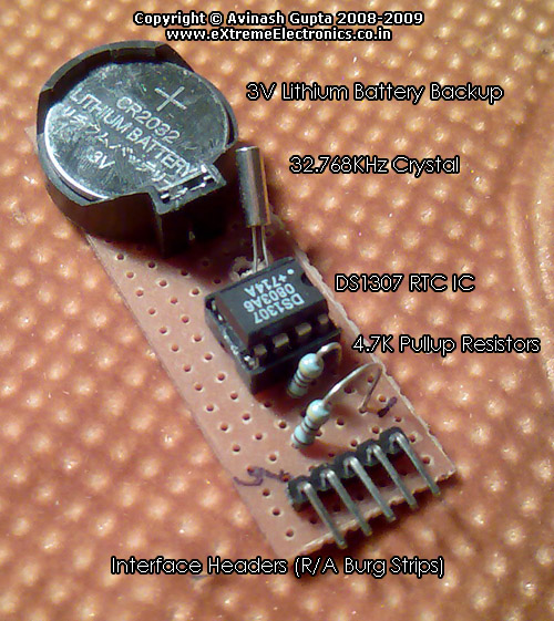 |
Fig. : A Simple DS1307 RTC Module. |
Once the application programmer has access to functions that reads and writes to any register (specified by its address) inside DS1307 ic, he/she can easily get and set the time infos like sec,min,hour, am/pm, date,month,year etc. The register access layer is built over the core Soft I2C layer. The register access layer consists of the following three functions.
void DS1307Init(void)
{
   SoftI2CInit();
}

/***************************************************

Function To Read Internal Registers of DS1307
---------------------------------------------

address : Address of the register
data: value of register is copied to this.


Returns:
0= Failure
1= Success
***************************************************/

BOOL DS1307Read(uint8_t address,uint8_t *data)
{
   uint8_t res;   //result

   //Start

   SoftI2CStart();

   //SLA+W (for dummy write to set register pointer)
   res=SoftI2CWriteByte(DS1307_SLA_W); //DS1307 address + W

   //Error
   if(!res) return FALSE;

   //Now send the address of required register

   res=SoftI2CWriteByte(address);

   //Error
   if(!res) return FALSE;

   //Repeat Start
   SoftI2CStart();

   //SLA + R
   res=SoftI2CWriteByte(DS1307_SLA_R); //DS1307 Address + R

   //Error
   if(!res) return FALSE;

   //Now read the value with NACK
   *data=SoftI2CReadByte(0);

   //Error

   if(!res) return FALSE;

   //STOP
   SoftI2CStop();

   return TRUE;
}

/***************************************************

Function To Write Internal Registers of DS1307

---------------------------------------------

address : Address of the register
data: value to write.


Returns:
0= Failure
1= Success
***************************************************/

BOOL DS1307Write(uint8_t address,uint8_t data)
{
   uint8_t res;   //result

   //Start
   SoftI2CStart();

   //SLA+W
   res=SoftI2CWriteByte(DS1307_SLA_W); //DS1307 address + W

   //Error
   if(!res) return FALSE;

   //Now send the address of required register
   res=SoftI2CWriteByte(address);

   //Error
   if(!res) return FALSE;

   //Now write the value

   res=SoftI2CWriteByte(data);

   //Error
   if(!res) return FALSE;

   //STOP
   SoftI2CStop();

   return TRUE;
}
The above code was very easy to write after we referred to figure 4, figure 5 and figure 6 on page 12 and 13 in DS1307 datasheet. The task was just to translate the image to respective calls to SoftI2C API. And we did some error checking as well. Mostly it was to verify the return value from SoftI2CWriteByte() which returns 1 if the slave sends ACK after the byte written. This indicates that the slave (DS1307 in this case) has successfully received the byte. In case we don’t get an ACK, we immediately return from the function returning a FALSE value to the caller. This ensures that the caller know if the function succeeded or failed.
After our register access layer is done we need to write the module that uses the function of register access layer and provide high level functions to get and set the followings :-
- Seconds
- Minutes
- Hours
- Date
- Month
- Year
This layer will be the RTC layer. Over the RTC layer we will finally write the application layer that uses the services of RTC layer and any UI layer to show time to the user. This application layer will also enable the user to set desired time. UI layer layer may be written using the following components.
- Alphanumeric LCD display driver for AVR.
- Graphical LCD driver for AVR.
- Matrix Keypad driver for AVR.
- Remote control driver for AVR.
Both the RTC layer and application layer will be done on coming tutorials.
Hardware for testing DS1307 routines.
Our reference hardware is xBoard V2.0 with 16×2 LCD module connected on LCD Port. The configuration is as follows :-
- Main MCU: ATmega32A PU
- Crystal: 16MHz
- Low Fuse Byte: 0xFF
- High Fuse Byte: 0xC9
- PA0-> SCL line
- PA1<-> SDA line
- DS1307 module built as shown here.
This simple demo program just shows you the time as sent by DS1307 module. For a freshly made module the time is set to 00:00:00. You cannot set the time with this demo program. That feature will be added on coming tutorials.
As soon as you will turn on the setup, the display will start with 00:00:00 and keep on increasing. Even if you turn off the setup, the DS1307 will keep counting by the power of back-up coin cell. So when you turn it on after 1 hour or so the, display will reflect that time!
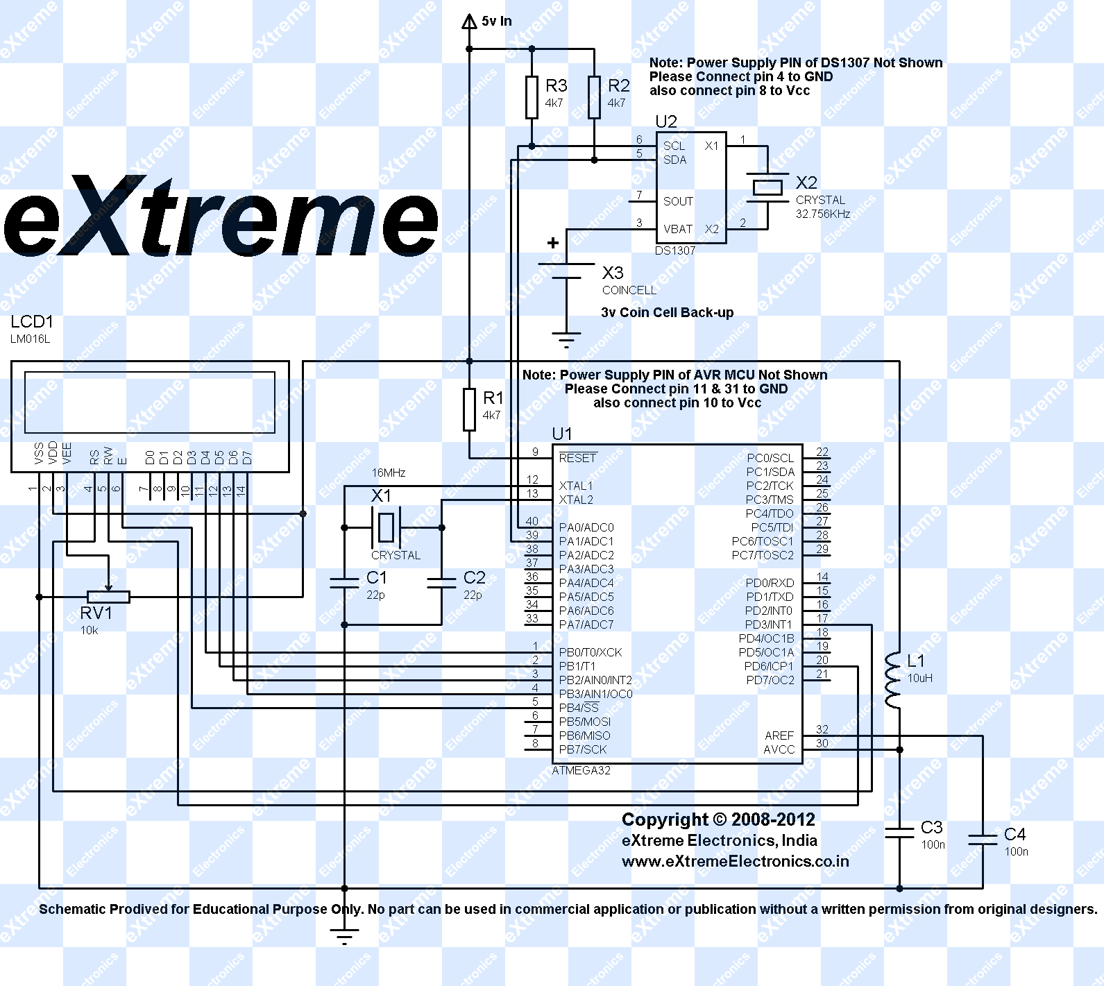 |
DS1307 Test Schematic |
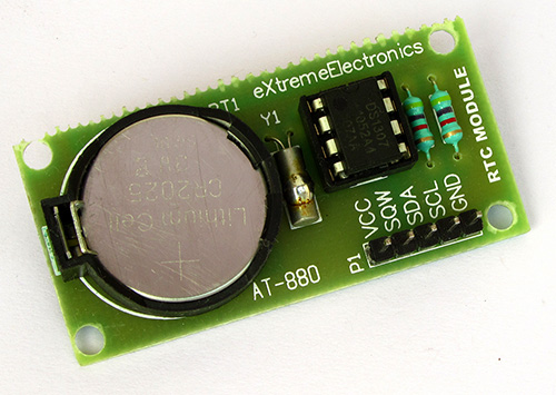 |
DS1307 Module |
Downloads for DS1307 interfacing
- Register access layer APIs (ds1307_soft_i2c.c and ds1307_soft_i2c.h)
- Complete demo to show time on LCD module.(AVR Studio Project with source files)
- Complete demo to show time on LCD module.(HEX File ready to burn)
- Proteus Simulation for DS1307 Soft I2C routines.
Help Us!
We try to publish beginner friendly tutorials for latest subjects in embedded system as fast as we can. If you like these tutorials and they have helped you solve problems, please help us in return. You can donate any amount as you like securely using a Credit or Debit Card or Paypal.
We would be very thankful for your kind help.
By
Avinash Gupta
Facebook,
Follow on Twitter.
www.AvinashGupta.com
me@avinashgupta.com
Pingback: Software I2C Library for AVR MCUs | eXtreme Electronics
As usual this another very nice tutorial. I am going to do all this stuff soon. And before that, I have a rough look on the text as well the code. I am just confused about SCL & SDA line which are PA0 & PA1 shown here. But on datasheet It is showing PC0 & PC1 are corresponding lines.Which one is correct?
depends on which microcontroller u r using
Thanks for soft i2c library. I am using ds1307 for reading seconds only and calculating minutes and hours But i am having problem that it read seconds for some time and whenever i connect other inputs like sensor to my project then RTC stop and couldent read seconds from it and RTC is stop even if other inputs are remove.
Hi!
I’ve been trying to run this little program on my Atmega8, but for some reason I can’t communicate properly with the RTC module. I want to ask, if there are any requirements for those libraries, to run them properly? Maybe the clock for the MCU has to be set to 16MHz?
My problem exactly: There is no error when I try to write something to register, also there’s none when I try to read a register, but the result is empty (0).
Ok, now I know what was the problem: too small pullup resistors. I put 10k instead of 4.7 (which are enough for 24c64) and the problem solved itself 😉
Pingback: Real Time Clock using ds1307 not updating the time
Hello Avinash,
After execution it is showing
1?:1?:1? AM
Can you please suggest what to be done?
Yes the problem is in your hardware, please use the prescribed hardware only !
I am using 8Mhz oscillator 🙁
Is there any option to use the same code on 8 Mhz?
No it runs only on 16MHz!
Hmmmmm Thanks for the quick reply
btw I need not use I2C for this on right?
Hello Avinash,
I tried with 16Mhz clock. Now it just displays
xBoard v2.0
00:00:00 AM
time is not being updated 🙁
@Avi,
Its a hardware problem. Please use xBoard v2.0 only !
Work like a charm! Many tks!!!
Hello Avinash sir,
Thanks a lot for this tutorial,
please tell me about how to get
Date Month Year on LCD.
Hello Avinash,
please send me the source file for ds1307 date & Time display on LCD.