Buy xBoard NOW !
Free shipping across India ! Pay Cash on Delivery ! 15 Days Money Back!
If you have played games on console you must be knowing what a joystick is. In games a joystick is generally used to control the motion of character or a vehicle (like plane or car). Joystick give a very realistic two dimensional control! Joystick are also used to control the motion of real objects like a robot or a car. Generally we want to control the back and forth motion of any object along with the ability to make it turn left and right. For this we use a common joystick with two axis. The y axis is used to move the object forward and backward, while the x axis is used to turn the object left or right. The type of joystick we are using in this article is an Analog Joystick that means it can give the magnitude of motion along with the direction. For example you can push the joystick little forward to make you robot start moving forward slowly. You can push the joystick further up to increase the speed of forward motion faster. Similarly you can control the speed of robot while making a reverse motion. Turning magnitude can also be controlled in the same way by moving the joystick left or right.
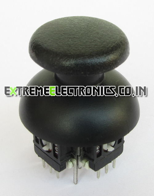 |
Fig. 1 – An Analog Joystick |
Working of Analog Joystick.
Analog joystick has two variable resistor for two axis. Each variable resistor has three pins, two extreme pins are connected to Vcc(5v in our case) and ground. The center pin is the output pin. The output voltage is between Vcc and GND depending on the position of stick. By measuring the voltage output of two variable resister from which the joystick is built, we can determine the position of stick in x and y axis.
Interface with AVR Micro.
As told above the position of stick can be determined by measuring the voltage from the output of the two variable resistor of the joystick. This can be easily done by using the ADC of AVR Microcontroller. The output of the two variable resistor of the joystick are connected connected with the two channels of ADC. The measurement can be easily done by using our ADC libraries’s ReadADC() function. The return value is between 0-1023, the mid point is 512, so we subtract 512 from the ADC reading. This finally gives us a value between -512 to +511.
      x=ReadADC(0);  //Read ADC Channel 0
      y=ReadADC(1);  //Read ADC Channel 1

      x=x-512;    //512 is the mid point
      y=y-512;
Joystick Wiring.
The joystick is wired as described in the image below. The two extreme points or both the variable resistor are connected to Vcc and Ground respectively. While the central pin provide output, which is connected to ADC input channel.
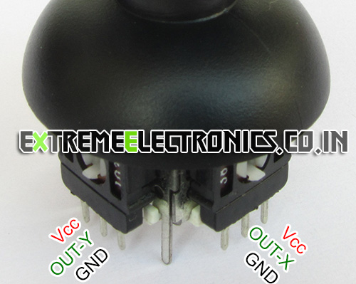 |
Fig. 2 – Analog Joystick Wiring |
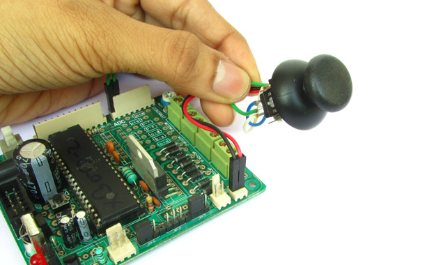
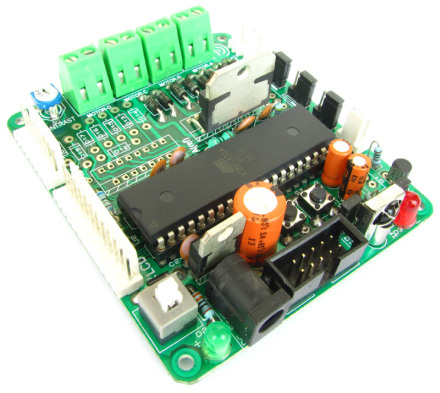
Connect both the Vcc together and connect them to 5v out point of your development board. Similarly connect both the grounds and connect them to ground point of your board. Connect out-x to ADC Channel 0, and out-y to ADC Channel 1. The images below shows the Vcc, GND, ADC0 and ADC1 pins.
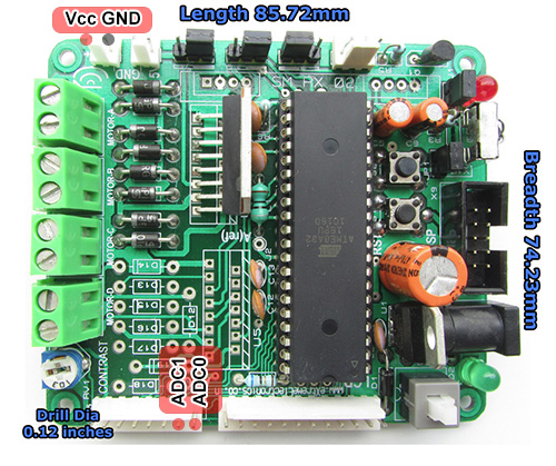 |
Fig. 3 – xBoard ADC Pins and Power Out Pins. |
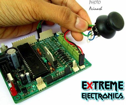 |
Fig. 4 – An Analog Joystick connected with xBoard v2.0 |
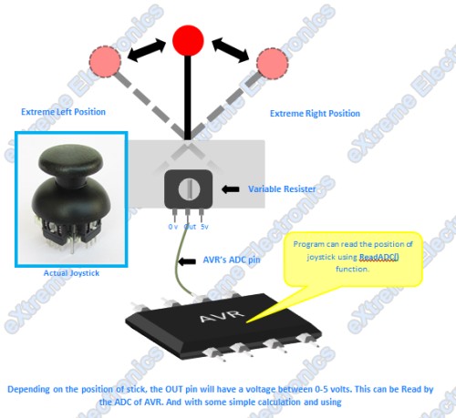 |
Fig. 5 – Interface with AVR |
The demo program reads the two axis of joystick and displays it in the LCD Module. The value range from -512 to + 511 for each axis. So attach an LCD Module as described in the xBoard Manual.
Demo Program for Joystick Interface.
The code is compiled using Atmel Studio 6 IDE. More information on using Atmel Studio 6.
/*
 * JoystickTest1.c
 *
 * Created: 19-10-2012 AM 11:14:54
 *  Author: Avinash
 */


#include <avr/io.h>

#include "lib/lcd/lcd.h"
#include "lib/adc/adc.h"

void Wait();

void Wait()
{
   uint8_t i;
   for(i=0;i<60;i++)
   {
      _delay_loop_2(0);
   }
}

int main(void)
{
   //Initialize LCD Module
   LCDInit(LS_NONE);

   //Initialize ADC Peripheral
   InitADC();

   //Welcome Message
   LCDWriteStringXY(0,0,"Joystick Test !");
   LCDWriteStringXY(0,1,"-Avinash");

   Wait();

   LCDClear();

    while(1)
    {
      int16_t x,y;

      x=ReadADC(0);  //Read ADC Channel 0
      y=ReadADC(1);  //Read ADC Channel 1

      x=x-512;    //512 is the mid point
      y=y-512;

      LCDWriteStringXY(0,0,"   Axis Data   ");
      LCDWriteStringXY(0,1,"X:      Y:       ");

      LCDWriteIntXY(2,1,x,4);
      LCDWriteIntXY(10,1,y,4);

      _delay_ms(250);
    }
}
Schematic for Analog Joystick Interface
 |
Fig. 6 – ATmega32 Analog Joystick Interface Schematic |
Important Note !
The program requires that the AVR MCU is clocked from an external 16MHz crystal. Caution should be taken as this is NOT the default clock source of ATmega32 shipped from factory. You need to change the fuse bits to change the clock source from internal 1MHz RC Oscillator to the external crystal. The fuse bytes to enable clocking by external crystal is :-
- LOW FUSE = 0xFF
- HIGH FUSE = 0xC9
 |
Fig. 7 – Setting the Fuse bytes. |
Related Articles
This demo makes use of our LCD Library please see the following tutorial for more information on LCD Modules and the library functions.
Troubleshooting
- NO Display on LCD
- Make sure AVR Studio Project is set up for clock frequency of 16MHz (16000000Hz)
- Adjust the Contrast Adj. Pot.
- Press reset few times.
- Power On/Off few times.
- Connect the LCD only as shown on schematic above.
- Compiler Errors
- Many people these days has jumped to embedded programming without a solid concept of computer science and programming. They don’t know the basics of compiler and lack experience. To learn basic of compilers and their working PC/MAC/Linux( I mean a desktop or laptop) are great platform. But embedded system is not good for learning about compilers and programming basics. It is for those who already have these skills and just want to apply it.
- Make sure all files belonging to the LCD Library are "added" to the "Project".
- Make sure all files belonging to the ADC Library are "added" to the "Project".
- The AVR Studio project Type is AVR GCC.
- Basics of Installing and using AVR Studio with avr-gcc is described in this tutorial
- General Tips for newbie
- Use ready made development boards and programmers.
- Try to follow the AVR Tutorial Series from the very beginning. (Remember the list spans four pages, page 1 is most recent addition thus most advance)
Downloads
Help Us!
We try to publish beginner friendly tutorials for latest subjects in embedded system as fast as we can. If you like these tutorials and they have helped you solve problems, please help us in return. You can donate any amount as you like securely using a Credit or Debit Card or Paypal.
We would be very thankful for your kind help.
By
Avinash Gupta
Facebook,
Follow on Twitter.
www.AvinashGupta.com
hello Avinash,
I am working on MPLAB X for PIC18F14K50. I need to program for ADC can u please help me in programming. I tried making the program but unfortunatly i could not get the ouput on th board.
please help me as possible. I will be waiting for your reply.
regards,
Jeet
Hi Avinash,
Is there a specific reason why this needs to run from an external crystal/osc. Would there be a problem if the built in crystal is used instead and the code is changed accordingly.
Look forward to your response.
Thanks
GS
@Girish Sarwal,
Yes their is a specific reason why we have used 16.000000MHz external crystal.
Because we use that crystal on all our development board.
And reason to use that in all our development board is to get maximum speed from CPU.
So is that clear now ?
Thanks Avinash,
I understand you are aiming at speeding the processor but beyond that I hope there is no other reason and one can safely use the internal crystal, as long as it suits the purpose. I hope using the internal crystal does not adversely affect the ADC or any other peripherals. Please advise.
@girish sarwal, your understanding is perfectly fine. You can definately use the internal oscillator. I have interfaced the same thing with atmega32 running @ 8 MHz internal oscillator. If u r developing ur own board then it is nice to reduce the external hardware by using the internal osc of avr
Thanks @jitesh
All done successfully. The ATMEGA-8 ADC is pretty sensitive to stray currents. All fixed now.
where is the adc library file??
Hello Avinash,
I’m a student of B.Sc. in electronic engineering and have a question which is: Can you help me to initial my dual shock joystick and connect it to my AVR based microprocessor. I know completely about compilers like Atmel Stadio and Codevision plus simulation softwares like Proteus and a bit familiar with serial communication and I2C protocol.
I’m very enthusiastic about having full access to 14 buttons joysticks and interfacing them for computer or android phones.
I hope for your prompt response, Thanks in advance.
Hello Avinash,
Firstly i’d like to thank you for this project. I tried this out by opening up a gamepad and using its joystick independently by making additional connections and disconnecting the old ones and it all worked out pretty fine.. However, could you please help me if i have to connect my Gamepad directly via the 4 wires of the USB to the Development Board, and make use of all the buttons (16) and both the joysticks via Atmega32.. Kindly help.. Looking forward to your reply.
Regards,
Anshul
@Anshul Mittal
Thanks for the feedback.
To connect USB Joystick you need a MCU with USB Host and a USB Host Stack (software)
Both are more complex than you can imagine !
Only available on 32bit platforms.
Can the same Program be used for atmega8 interfacing….??
Hi Avinash
First, i wanna really thank you for this great project.I have a graduation project which is a bit similar to this one, but in my project i need three dimensional control unlike this one. To be more precise i need to control a 3d shape drawn on pc monitor by a microcontroller with a joystick or three A/D input. What else should i do for that? Do i need to use this same process and just make some additions to make this three dimensional or do i need a whole different process? I would be really appreciated if u help me even if i can have some ideas about this that would be enough.Thanks in advance. Looking forward for your reply.
Hi all,
How to speed control of dc motor using analog joystick and pwm mode.