Real Time Clocks, as the name suggests are clock modules. They are available as integrated circuits (ICs) and manages timing like a clock. Some RTC ICs also manages date like a calendar. The main advantage is that they have a system of battery backup which keeps the clock/ca lender running even in case of power failure. A very small current is required for keeping the RTC alive. This in most case is provided by a miniature 3v lithium coin cell. So even if the embedded system with RTC is powered off the RTC module is up and running by the backup cell. This same technique is used in PC timing also. If you have opened your computer case you will notice a small coin cell in the mother board.
In this tutorial we will learn to use a very famous RTC IC named DS1307. The DS1307 is described in the datasheet as follows
The DS1307 is a low-power clock/calendar with 56 bytes of battery-backed SRAM. The clock/calendar provides seconds, minutes, hours, day, date, month, and year information. The date at the end of the month is automatically adjusted for months with fewer than 31 days, including corrections for leap year. The DS1307 operates as a slave device on the I2C bus.
So the aim of the project will be to access the DS1307 registers, read time
- Access the DS1307 registers i.e. read/write data to/from the DS1307 IC
- Format the read data and display in LCD
- Ability to get time from user and store it to DS1307. This provide means to setup the RTC module with correct time.
DS1307 Internal Registers
From software point of view the DS1307 is just a collection of some 8 bit registers. You can read these register to obtain the current time and date. You can also modify them to hold the correct time. After that the DS1307 keeps then updated with current date and time. The following registers are there.
| ADDRESS | BIT7 | BIT6 | BIT5 | BIT4 | BIT3 | BIT2 | BIT1 | BIT0 | FUNCTION | RANGE |
| 00H | CH | 10 SECONDS |
SECOND |
SECOND |
00-59 | |||||
| 01H | 0 |
10 MINUTES |
MINUTES |
MINUTES |
00-59 | |||||
| 02H | 0 |
12 |
10HR |
10HR |
HOUR |
HOUR |
1-12+AM/PM OR |
|||
24 |
am/pm |
|||||||||
| 03H | 0 |
0 |
0 |
0 |
0 |
DAY |
DAY |
01-07 | ||
| 04H | 0 |
0 |
10 DATE |
DATE |
DATE |
01-31 | ||||
| 05H | 0 |
0 |
0 |
10MONTH |
MONTH |
MONTH |
01-12 | |||
| 06H | 10 YEAR |
YEAR |
YEAR |
00-99 | ||||||
| 07H | TO KEEP THINGS SIMPLE I HAVE SKIPPED THE CONTROL REGISTER THIS IS USED FOR SQUARE WAVE GENERATION ON PIN7 |
|||||||||
| 08-3FH | 56 BYTE RAM | 00h-FFh | ||||||||
The register uses BCD (Binary Coded Decimal) for storing the values. For example take register at address 01h, it stores the MINUTES. Say it is 37 minutes. Then it will be stored as follows.
 |
Fig. : BCD Format in DS1307 Registers. |
The DS1307.c and DS1307.h provide easy access to order generic viagra the registers. I have provided just two functions that allows you to read and write the DS1307 registers.
/***************************************************

Function To Read Internal Registers of DS1307
---------------------------------------------

address : Address of the register
data: value of register is copied to this.


Returns:
0= Failure
1= Success
***************************************************/

uint8_t DS1307Read(uint8_t address,uint8_t *data)


/***************************************************

Function To Write Internal Registers of DS1307
---------------------------------------------

address : Address of the register
data: value to write.


Returns:
0= Failure
1= Success
***************************************************/
uint8_t DS1307Write(uint8_t address,uint8_t data)
These functions depends on the I2C library. The I2C (Inter IC Communication) is a popular communication protocol between ICs. The DS1307 and our AVR ATmega8 communicates using the I2C bus. I will give more details on I2C in a separate tutorial.
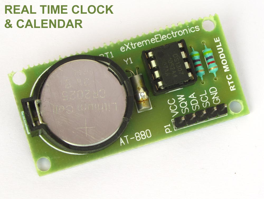
A Simple RTC Module
The DS1307 require an 32.768KHz crystal, a 3v lithium battery and 2 pull up registers to function. So I will make a small PCB that will hold all these. The image of module is shown below. The module can be connected to development boards using female-female burg wires.
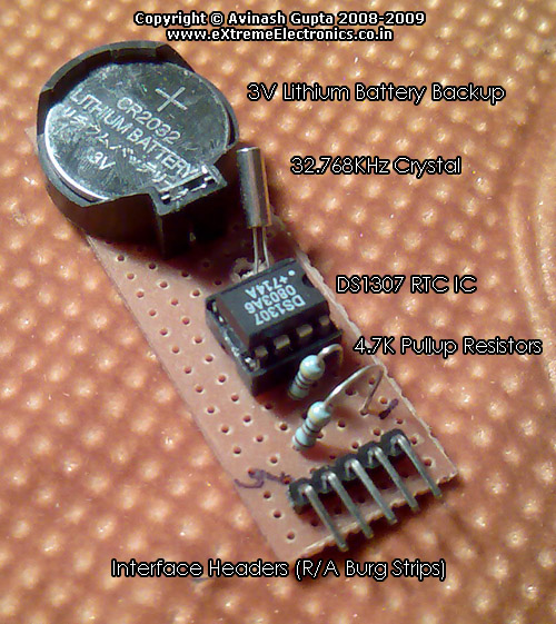 |
Fig. : A Simple DS1307 RTC Module. |
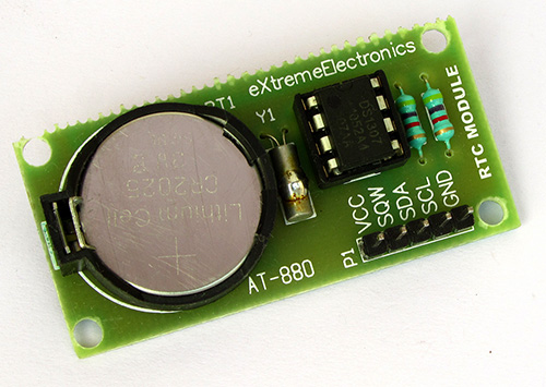 |
Professional DS1307 RTC Module |
 |
Fig. :DS1307 RTC Module Circuit Diagram. |
Once you have the RTC Module ready you can connect it with your favorite MCU like PIC or AVR or any other MCU. In this tutorial I will connect it with AVR ATmega8 MCU, I will also interface it with PIC MCUs latter on.
AVR ATmega8, DS1307 RTC Interface Example with LCD Module
To make a complete usable example we will connect a 16×2 LCD Module, and 3 push buttons. The detailed circuit diagram is given below.
 |
Fig. :AVR ATmega8 RTC Interface Circuit Diagram. |
avr-gcc software
The full software for the example is written in C language and compiled with avr-gcc. The whole software is very modular. Following software modules are used.
- LCD Interface modules for handling the display device.
More detail is given on these pages.
- LCD Interfacing library for Atmel AVR MCUs
- LCD Interfacing library for Microchip PIC MCUs
- Low Level I2C Interface Library. This handles the data
communication using the hardware I2C module present inside AVR/PIC MCUs.
- For Atmel AVR MCUs (Yet to be written)
- For PIC16 MCUs.(Yet to be written)
- For PIC18 MCUs.(Yet to be written)
- DS1307 Module : This module built on top of above I2C module help in reading/writing data to and from the DS1307 chip. Functions are very simple and documented inside the .c and .h files itself.
- The main application module RTC.c is the application software that uses the above modules to communicate with both the LCD and DS1307 chip. It also manages the handling of UI (User Interface) by the help of 3 push buttons.
Fabrication Instructions
Assemble the circuits according to the circuit diagrams shown above. Burn the hex file (download link given at the end of article) to an ATmega8 using a suitable programmer. Set the fuse byte as follows LOW=21 HEX HIGH=D9 HEX . Apply power to the circuit and adjust the LCD Contrast Pot until the display is clear. The initial time should be shown as 00:00:00. Now press the "menu" key to enter the main menu. Use the LEFT and RIGHT Key to move between options and ENTER to select an item. The main menu has the following options.
- Set Time
- Set On Time (NOT IMPLEMENTED YET)
- Set Off Time (NOT IMPLEMENTED YET)
- Quit
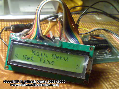 |
Fig. : The Main Menu. |
Go to the "Set Time" option, the following UI will be displayed.
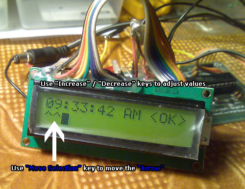 |
Fig. : Setting the time. |
Use the "Move Sel" key to move between Hour,Minute,Second,AM/PM, and <OK>. Use the "Increase"/"Decrease" buttons to adjust value. Finally go to <OK> and press any key. A message will be shown, "Main Time Set". The main menu will return. Select "Quit" from the main menu and the main screen showing the current time will be displayed. Now the RTC is setup, it will keep the time even if you switch off the circuit. Next the you power up the circuit it will still show the REAL time!
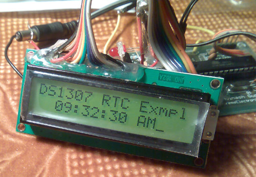 |
Fig. : DS1307 RTC Example Main Screen. |
Downloads
A Request From Readers
If you find this article useful or have any doubts or want to share your valuable suggestions, please leave a comment or two ! I would be glad to hear from you.
-The Author
Avinash Gupta
Videos
The ATmega8 DS1307 RTC Interface example in action.
I just finished my first project using the DS1307, and I appreciate your idea of building the complete module on perf board. I think I might go back and do that… 🙂
There is a way around needing the pull-up resistors on the clock module (at least with an ATMEGA168): Set the SCL and SDA lines high, which enables pull-up resistors inside the controller. I only know how to do this in the Arduino environment, but I do know that it’s possible.
I also used the SRAM, which was super convenient for when I wanted to be able to reset the atmega, but be able to pick up from where I left off.
http://kennethfinnegan.blogspot.com/2009/10/arduino-temperature-logger.html
I can not simulate this circuit in Proteus. It does not work.
I don`t understand why. Please? help.
This is an excellent article! Detailed description suitable also for beginners. I will not build this project but I enjoyed a lot reading it.
Hi Avinash
This is my favourite Chip (DS1307)
I know it pretty Good
I give a Lib for my friend
for BCD->BIN
*sec = ((*sec & 0xF0) >> 4)*10 + (*sec & 0x0F);
*mnt = ((*mnt & 0xF0) >> 4)*10 + (*mnt & 0x0F);
*hr = ((*hr & 0xF0) >> 4)*10 + (*hr & 0x0F);
*day = ((*day & 0xF0) >> 4)*10 + (*day & 0x0F);
*year = ((*year & 0xF0) >> 4)*10 + (*year & 0x0F);
*date = ((*date & 0xF0) >> 4)*10 + (*date & 0x0F);
*mn = ((*mn & 0xF0) >> 4)*10 + (*mn & 0x0F);
for BIN->BCD
_I2C_write(((sec/10)<<4) + (sec%10));
_I2C_write(((min/10)<<4) + (min%10));
_I2C_write(((hour/10)<<4) + (hour%10));
///////////////////////////////////////////////////////////
////Read Ram
unsigned char rtc_read(unsigned char address_)
{
unsigned char data_;
_i2c_start();
_i2c_write(0xd0);
_i2c_write(address_);
_i2c_start();
_i2c_write(0xd1);
data=_i2c_read(0);
_i2c_stop();
return data_;
}
///
void rtc_write(unsigned char address,unsigned char data)
{
_i2c_start();
_i2c_write(0xd0);
_i2c_write(address);
_i2c_write(data);
_i2c_stop();
}
void rtc_init(unsigned char rs,unsigned char sqwe,unsigned char out)
{
rs&=3;
if (sqwe) rs|=0x10;
if (out) rs|=0x80;
_i2c_start();
_i2c_write(0xd0);
_i2c_write(7);
_i2c_write(rs);
_i2c_stop();
}
void rtc_get_time(unsigned char *hour,unsigned char *min,unsigned char *sec)
{
_i2c_start();
_i2c_write(0xd0);
_i2c_write(0);
_i2c_start();
_i2c_write(0xd1);
*sec=bcd2bin(_i2c_read(1));
*min=bcd2bin(_i2c_read(1));
*hour=bcd2bin(_i2c_read(0));
_i2c_stop();
}
void rtc_set_time(unsigned char hour,unsigned char min,unsigned char sec)
{
_i2c_start();
_i2c_write(0xd0);
_i2c_write(0);
_i2c_write(bin2bcd(sec));
_i2c_write(bin2bcd(min));
_i2c_write(bin2bcd(hour));
_i2c_stop();
}
void rtc_get_date(unsigned char *date,unsigned char *month,unsigned char *year)
{
_i2c_start();
_i2c_write(0xd0);
_i2c_write(4);
_i2c_start();
_i2c_write(0xd1);
*date=bcd2bin(_i2c_read(1));
*month=bcd2bin(_i2c_read(1));
*year=bcd2bin(_i2c_read(0));
_i2c_stop();
}
void rtc_set_date(unsigned char date,unsigned char month,unsigned char year)
{
_i2c_start();
_i2c_write(0xd0);
_i2c_write(4);
_i2c_write(bin2bcd(date));
_i2c_write(bin2bcd(month));
_i2c_write(bin2bcd(year));
_i2c_stop();
}
anyone using SW I2C on other pins like scl and sda, i need simple function for i2c_write, i2c_start, i2c_read??
thanks for help
Dear Sir,
I made a clock as per your design and used a hex file given by you but it just shows a cursor blinking on lcd and nothing else .
I like this project and i want to do this but ………..
Please help to solve this ……………
Thanking You……………
Praful
09881303008
@Praful
When I published this project (or any other) I took GREAT CARE and try to give as much information as possible to SUCCESSFULLY make the project. I feel really pity at you that u could not make it 🙁 May be some people are really too low on patience to ask at once that the thing is not working. The project is already a kind of like SPOON FEEDING a baby. I can’t do more than this.
I would say this would be because your SDA and SCL wires from your rtc chip are not connected to the SDA and SCl on the micro correctly. check the data sheet to see which pins they correspond to.
For those who use proteus ISM for simulation:
– Program does not work well with proteus, there is a bug in simulation tool which does not work well with this function in I2C.C, I2CStop() function:
//Wait for STOP to finish
while(TWCR & (1<<TWSTO));
Replace this by this:
//Wait for STOP to finish
_delay_loop_2(500);
It will work.
Do not update library code while working with hardware. There is a bug in proteus not with code.
dude.please complete the rf communication between microcontrollers.still waiting for that………….
Great!!! Thanks…. Fully Explained ….Very nice Comments…
quiet brief stuff, nicely explained..!!
hi avinash, can you help me in interfacing atmega8 with PT2258. basicaly it’s a hometheatre project.
thanks in advance.
Hi Avinash,
I feel that there is a bug in the circuit that you have given.
In the first image(in DS1307 Circuit), it is given that the SCL pin to be connected to the SDA pin of the MCU and SDA to SCL of the MCU. But the SCL pin of an I2C device should be connected to the SCL pin of any other I2C Device. I think this is a bug and please verify the same…
Awaiting reply…..
Thank You
hi,
I made a project only to read DS1307 after every 1sec and for that i took your code as a reference. I checked the hardware & everything is OK, but the RTC update the time only once.Please reply…..
thank you
I made this circuit and code in proteus for simulate it, but I can not do it. I shall apreciate if someone can send me a file in proteus. and other question is why there are many code windows when I opened in avrStudio 4?, it can simulate or I need to add every code windows? please help me, sorry I’m novice, but I’ll try to do it. thanks a lot
Dear Avinash Sir,
This program is too good.This is my first AVR success program and LCD display program.Sir how I develop the 128×64 LCD display.Give the circuit diagram with program.I am also a customer of AVR kit.Thanks again.
hello sir,
i am working on a project using PIC 16F877. can u help me for writing code for interfacing DS1307 with PIC using instructions only and not in c-language.
please reply…
thank u.
I go along with you actually, I believe! Might this become doable for you to have your blog translated directly into Russian? English is actually my own 2nd language.
hello avinash
I have a doubt… does the line
Time[0]=48+((temp1 & 0b00010000)>>4);
perform the function of converting bcd value to binary? how does it work exactly? (esp addind 48)
Awaiting a reply
Thanks n regards
Debbie
Hello Debbie,
You could easily get that line if you know C well! The time is a string. So Time[0] is actually the 10th part of the hour. So if time is 11:00:00 AM then Time[0] is ‘1’ and if time is 03:15:24 PM then Time[0] is ‘0’ note that as Time[] is a string each element of this array is in ASCII. If you consult the ASCII Table you will note that numbers starts after 48 in ASCII table so ASCII code of ‘0’ is 48 and ‘1’ is 49 and so on. So 48 is added to it.
If you look at DS1307 register table given above you will find out that 10th position of hour is stored in 5th BIT HOUR register. And since we are running in 12hour mode the 10th position can only be 0 or 1. It is 0 when time is from 1 to 9 and 1 when time is from 10 to 12. So just one bit is required. And since hour reg holds other values too, so to extract only the tenth part we are ANDING it with binary 00010000 (written as 0b00010000 so the compiler can get its binary number). so now all BITs are set to 0 execpt the fifth bit. Which is either 0 or 1 as in original REG. Now we shift this value to 4 places to left. This bring this bit to the 0th position. Now we add 48 to it to get an ASCII equivalent.
All this were just requires knowledge of basic computing and C programming nothing special. Before you delve into embedded be a good programmer first.
I have been coding since my childhood with Logo and Basic languages!
Using the number 48 is generally bad form when doing this kind of conversion. If you really knew C well, you would be using ‘0’ instead of the literal 48. Then it becomes pretty obvious that you’re adding an offset to the ASCII 0 character.
@Kenneth,
Great Advice! Thanks!
hi kunel
thank u very much for your program
but i have problem with that
i use this version of cv avr:2.03.4 standard
when i compile your program,i see this error
Error: D:\documents … : MISSING ‘(‘
and this error comes back to this line;
uint8_t hr_,hr_set,min_,min_set,sec_,AMPM,AMPM_set,hr_clr,min_clr,AMPM_clr,alarm=0,temp1;
what shoud i do about this?
this is my email:
lithium.amir@yahoo.com
please help me
as soon as posible…
Great job Avinash.
Keep doing it…
Well done,
it’s an easy job to get it run with your good description.
very good explanation
I’ll start making this project
thanks alot
Wow, congratulations on projects are great!
I’ve learned a lot from them.
Thanks
Ja mounted the relay and the timer clock, very good!
Att
André
ah, another thing, by any chance you come to complete the items
menu?
if anything, could post? I would like to mount the clock
with alarm, to turn something! interesting
thanks
André
@AV
Got it working on an atmega32/16.. Had to re-fuse it to default values (1MHZ) -> Lfuse E1 Hfuse D9 Lock 3F. I couldnt get it to work at 16MHZ. Anybody got a solution? Also.. wheres my 20×4 LCD support? :o)
BTW I found this EXCELLENT avrdude GUI > Google “SinaProg 1.6.5.10” for an excellent avrdude gui. Best Ive seen so far.. by a long shot. I have to use this till I get an avrstudio 4 compatible prog.
Also, The way youve got the ds1307 hooked up in your schematic (above) doesnt work – at least for me. It did work after I hooked up: PIN4 -> GND / PIN8 -> VCC / also used 10k resistors as pullups on SDA, SCL line eventhough 4.7k no doubt works fine as well.
Thanks again Av. I see what you mean now by “portability”.
@wlewis,
Latest version of LCD Library comes bundled with the RFID Demo which can be downloaded from the following link.
https://extremeelectronics.co.in/avr-tutorials/interfacing-rfid-reader-with-avr-mcus-avr-tutorial/
As for the power pins of DS1307 they muct be connected. CAD packages (used to draw the schematic) hides those pins and connect them internally. Thats why they are not shown
@Av
Im getting a lot of flicker on the atmega32.. any ideas?
@wlewis,
thats becasue you are running slow, the program is for 16MHz i remember.
hai
i am now planning to make “interfacing Ds1307 with Atmega8”.
but i have avr development with me.so wat all changes that i should make so as to do the same using avr development board.i am having atmega32 on ma board.also i am planning to use a eeprom ic to use the facilities of on timer & off timer.In one of the replys by kunal,i have saw the code for that.bt iwant to know if any library is needed for reading/eriting into the eeprom memory.i am using the eeprom 24C64.
hey av can i just put the 24c64 eeprom & ds1307 rtc in the same sda,scl line of atmega8 by using your routines for bth of them,or do i have to apply some other tricks as well?i need a eeprom and a rtc simultameously in a circuit.as i think its a fundamental question,expecting a lot from you.yhnx.
@Sayantan,
Yes you can connect a ds1307 and upto 8 24C64A ICs on same line. Just need to make sure each 24C64A is on separate address. Use PIN A0,A1,A2 to set address of each 24C64A IC. You have to give binary number equivalent to the address required.
thnx for the info.but i’m doing a data logger project,where on the sda,scl line of atmega8 ,one ds1307 & one 24c64 eeprom are connected.RTC runs well generally,bt when the eepromwrite() function is being executed, the time on the screen is halted.next time i powering on the circuit,the date and time are shown is completely changed.so,my question is when the rtc is showing time & date on the 16×2 lcd screen,can i access the eeprom(read & write),or i have to do some other coding for that? that’s why i was asking you if i can connect the ds1307 & 24c64eeprom in the same sda,scl linei’m completely using your rtc & eeprom routines.individually they are fabulous.so i.ve a big hope upon you.pls do rply.
and what about the addres lines.i think that would be useful when we are using multiple eeproms in same sda,scl line.bt in this case there is one ds1307 & one 24c64 eeprom.so how can i utilise the address lines?
Hello Satyam,
By reading at your comment I came to know that you have worked on data logger. I want a data logger for my project can you please mail me the report?
It will be of great help from your side.
avi22491@gmail.com
Hello, Avinash! I’ve assembled an another device with DS1307 RTC. Your code was helpful for me indeed! Thanks a lot. But there’s one thing that don’t work at all – time format changing. I learned its datasheet several times but sill couldn’t find out. When I set up time like this 19:59:50 – it’s work perfect and show correctly, but after 10 seconds it’s changed to a wrong format 00:00:00. What’s the matter ? Can you give me advice? It seems that your library has restrictions or mistakes, but it’s just my opinion.
With best wishes from Russia !
Code from my project:
int main( void )
{ _delay_loop_2(0);
_delay_loop_2(0);
IND_Init(); // ??????????
OWI_Init(BUS); //1-wire bus
//Initialize I2C Bus
I2CInit(); //i^2c
//Clear CH bit of RTC
#define CH 7
uint8_t hr,min,sec,am_pm,temp;
DS1307Read(0x00,&temp);
//Clear CH Bit
temp&=(~(1<<CH));
DS1307Write(0x00,temp);
//Set 12 Hour Mode
// DS1307Read(0x02,&temp);
//Set 12Hour BIT
// temp|=(0b01000000);
//Write Back to DS1307
// DS1307Write(0x02,temp);
hr=19;
min=59;
sec=50;
//am_pm=1;
//Now write time back to RTC Module
temp=((sec/10)<<4)|(sec%10);
DS1307Write(0x00,temp);
temp=((min/10)<<4)|(min%10);
DS1307Write(0x01,temp);
temp=((hr/10)<<4)|(hr%10);
DS1307Write(0x02,temp);
// if(am_pm)
// {
// temp|=0b00100000;
// temp|=0b00000000;
// }
// temp=0b01100001;
// DS1307Write(0x02,temp);
// uint8_t i;
// for(i=0;i<10;i++)
_delay_loop_2(0);
…
}
Oops ! sorry, for a fast previous comment. My problem has already solved !
DS1307Read(0x02,&temp);
hr=(((temp & 0b00010000)>>4)*10)+(temp & 0b00001111);
|
reading only 4 bit ——-
Hello sir, as you completed this project i am asking the problem that i am facing. when i set time i.e. 12:50:38 PM and i connect 3v dc supply to rtc between +ve on 3rd and -ve on 4th and 4th is grounded. But it still shows 12:50:38 PM. The time is not increasing or probably rtc is not working. For 3 volt battery i am using 2 pencil cells made o Zinc Chloride that gives 3 volt dc. I have measured it by mutimeter also. 8th pin of rtc is given vcc. 5th and 6th pins are connected to 4.7k resistor and to vcc. crystal oscillator is connected between first and second. I have also connected 4.7k resistor to 7th pin and to vcc. plz help.
Just appreciate you to publish your knowledge. All the best. Well done!!
sorry i cant find the Ds1307.h and c files were can i download it
thank you
Hi,
I assembled the clock and it works fine for both DS1307 and DS2131 chips. This second one is newer but it works with software aou provided. I compared precision with stopwatch and it was accurate exept when I turn off and on again. After few off-on’s RTC (both chips equally) were late cca 3 sec. So, it seems to me that something happends with rtc during on-off that causes delay. Did anyone notice this, is it normal, and can something be done about it?
Thanks, regards…
@Filip,
Thanks for the fine observation. I have too noticed some problems like that but don’t know the real cause. Please, if you or someone finds some clues then please share it.
It seems to me that for some reason oscillator stops for a while when pow is switched off-on. In what moment and why I don’t know. In AN from Maxim they said oscilattor can stop when in battery mode if voltage on RTC inputs are higher than battery voltage. So I tought mabye microcontroller sends some pulses after supply is switched from 5V to batt. But it doesn’t make sense because rtc supply and inputs are on same line.
Pingback: Software I2C Library for AVR MCUs | eXtreme Electronics
Pingback: DS1307 I2C RTCC Interface using SoftI2C lib | eXtreme Electronics
Dear Avinash Gupta,
First I would like to say gratulations and thank you about your website and projects! They are very useful and great solutions!
I would like to ask you about this DS1307 project. Is it possible to save a given time point in DS1307? (Beside the current time, I would store an alarm time.)
If it is possible could you explain me how?
You mentioned that it is also can handle and following dates, calendars as well. How does it possible to store date and read it back?
Really really thank you your help!
Have a nice day and good projects.
Regards,
Gabor
hi
I am an electrical engineer
Interested in AVR
I’m happy to help you in this area
h_shahsavar@yahoo.com
Hi Avinash Gupta
I just test your circuite with some modification to run on atmega16.
At first i got in troble. finally by connecting SDA pin of DS1307 to SDA pin of Micro and also SCL pin of DS1307 to SCL pin of Micro my problem solved. In your shematic you connected them in reverse. I mean you connected SDA to SCL and SCL to SDA.
Regards
Ali Hassanpour
Hi,
I assembled the clock and reprogrammed it a bit so it shows time, date, day in a week.
On display, there is always a blinking cursor.
How can I remove it? I want display to show only data, without blinking cursor.
Have any idea?
Thanks a lot!
Regards
@Filip
Can you share a pic (or video) and your modified code ?
yes, no problem. I just altered your rtc.c file. First line of display shows time and second date, month , year and day in a week. Days in week are named in Croatian 😉 , so this need to be cahnged.
On menu I added “set date” where you can set all these parameters.
It works fine, I plan to add temp and humidity and make little weather station.
Here’s the code.
RTC.c:
#include
#include
#include “I2C.h”
#include “lcd.h”
#include “ds1307.h”
void ShowMainMenu();
void SetTime();
void Wait()
{
uint8_t i;
for(i=0;i<20;i++)
_delay_loop_2(0);
}
uint8_t PREV_PINB=0xFF;
/*
Function to test the current status of keys(0 to 2)
returns
0 if NOT pressed
1 if Pressed
*/
uint8_t GetKeyStatus(uint8_t key)
{
return (!(PINB & (1<<key)));
}
/*
Function to test the previous status of keys(0 to 2)
returns
0 if NOT pressed
1 if Pressed
*/
uint8_t GetPrevKeyStatus(uint8_t key)
{
return (!(PREV_PINB & (1<<key)));
}
void main()
{
//Wait Util Other device startup
_delay_loop_2(0);
_delay_loop_2(0);
//Initialize the LCD Module
LCDInit(LS_BLINK);
//Initialize I2C Bus
I2CInit();
//Enable Pull ups on keys
PORTB|=((1<<PB2)|(1<<PB1)|(1<<PB0));
//Clear CH bit of RTC
#define CH 7
uint8_t temp;
DS1307Read(0x00,&temp);
//Clear CH Bit – Clock Halt bit=0
temp&=(~(1<>4);
Time[5]=’:’;
DS1307Read(0x01,&data);//minute
Time[4]=48+(data & 0b00001111);
Time[3]=48+((data & 0b01110000)>>4);
Time[2]=’:’;
DS1307Read(0x02,&data);//sati
Time[1]=48+(data & 0b00001111);
Time[0]=48+((data & 0b00110000)>>4);
LCDWriteStringXY(0,0,Time);
DS1307Read(0x06,&data); //godina
Date[8]=”;
Date[7]=48+(data & 0b00001111);
Date[6]=48+((data & 0b11110000)>>4);
Date[5]=’/’;
DS1307Read(0x05,&data); //mjesec
Date[4]=48+(data & 0b00001111);
Date[3]=48+((data & 0b00010000)>>4);
Date[2]=’/’;
DS1307Read(0x04,&data); //dan u mjesecu
Date[1]=48+(data & 0b00001111);
Date[0]=48+((data & 0b00110000)>>4);
LCDWriteStringXY(0,1,Date);
DS1307Read(0x03,&data); //dan u tjednu
Dan=data & 0b00000111;
switch (Dan)
{
case 1 : LCDWriteStringXY(9,1,”Pon”); break;
case 2 : LCDWriteStringXY(9,1,”Uto”); break;
case 3 : LCDWriteStringXY(9,1,”Sri”); break;
case 4 : LCDWriteStringXY(9,1,”Cet”); break;
case 5 : LCDWriteStringXY(9,1,”Pet”); break;
case 6 : LCDWriteStringXY(9,1,”Sub”); break;
case 7 : LCDWriteStringXY(9,1,”Ned”); break;
}
/*//AM/PM
if(data & 0b00100000)
{
LCDWriteStringXY(0,1,”Poslije podne”);
}
else
{
LCDWriteStringXY(0,1,”Prije podne “);
}
*/
//Wait Some time and keep testing key input
uint8_t i;
for(i=0;i<20;i++)
{
if(GetKeyStatus(2))
{
//Go To Main Menu
ShowMainMenu();
_delay_loop_2(0);
_delay_loop_2(0);
_delay_loop_2(0);
}
_delay_loop_2(5000);
}
}
}
void ShowMainMenu()
{
//The Main Menu
char *menu_items[]={ "Set Time",
"Set Date",
"Quit"
};
uint8_t menu_count=3;
uint8_t selected=0;
_delay_loop_2(0);
_delay_loop_2(0);
while(1)
{
LCDClear();
LCDWriteString(" Main Menu ");
LCDWriteStringXY(2,1,menu_items[selected]);
LCDWriteStringXY(0,1,"”);
if(GetKeyStatus(1))
{
//Left Key(No 1) is pressed
//Check that it was not pressed previously
if(!GetPrevKeyStatus(1))
{
if(selected !=0)
selected–;
}
}
if(GetKeyStatus(0))
{
//Right Key(No 0) is pressed
//Check that it was not pressed previously
if(!GetPrevKeyStatus(0))
{
if(selected !=(menu_count-1))
selected++;
}
}
if(GetKeyStatus(2))
{
//Enter Key Pressed
//Check that it was not pressed previously
if(!GetPrevKeyStatus(2))
{
//Call Appropriate Function
switch (selected)
{
case 0:
SetTime();
break;
case 1:
SetDate();
break;
case 2:
return;//Quit
//case 3:
// return;//Quit
}
}
}
PREV_PINB=PINB;
_delay_loop_2(5000);
}
}
void SetTime()
{
uint8_t hr,min,sec,temp;
//Read the Second Register
DS1307Read(0x00,&temp);
sec=(((temp & 0b01110000)>>4)*10)+(temp & 0b00001111);
//Read the Minute Register
DS1307Read(0x01,&temp);
min=(((temp & 0b01110000)>>4)*10)+(temp & 0b00001111);
//Read the Hour Register
DS1307Read(0x02,&temp);
hr=(((temp & 0b00110000)>>4)*10)+(temp & 0b00001111);
uint8_t sel=0;
while(1)
{
LCDClear();
LCDWriteString(“00:00:00 “);
LCDWriteIntXY(0,0,hr,2);
LCDWriteIntXY(3,0,min,2);
LCDWriteIntXY(6,0,sec,2);
//Draw Pointer
LCDWriteStringXY(sel*3,1,”^^”);
//Input Up key
if(GetKeyStatus(1))
{
if(!GetPrevKeyStatus(1))
{
if(sel==0)
{
//Hour
if(hr==24)
{
hr=0;
}
else
{
hr++;
}
}
if(sel==1)
{
//Min
if(min==59)
{
min=0;
}
else
{
min++;
}
}
if(sel==2)
{
//Sec
if(sec==59)
{
sec=0;
}
else
{
sec++;
}
}
if(sel == 4)
{
//OK
break;
}
}
}
//Input Down
if(GetKeyStatus(0))
{
if(!GetPrevKeyStatus(0))
{
if(sel==0)
{
//Hour
if(hr==0)
{
hr=23;
}
else
{
hr–;
}
}
if(sel==1)
{
//Min
if(min==0)
{
min=59;
}
else
{
min–;
}
}
if(sel==2)
{
//Sec
if(sec==0)
{
sec=59;
}
else
{
sec–;
}
}
if(sel == 4)
{
//OK
break;
}
}
}
if(GetKeyStatus(2))
{
if(!GetPrevKeyStatus(2))
{
//Change Selection
if(sel==4)
sel=0;
else
sel++;
}
}
PREV_PINB=PINB;
_delay_loop_2(30000);
}
//Now write time back to RTC Module
temp=((sec/10)<<4)|(sec%10);
DS1307Write(0x00,temp);
temp=((min/10)<<4)|(min%10);
DS1307Write(0x01,temp);
temp=((hr/10)<<4)|(hr%10);
temp&= ~(0b01000000); // 24 satno vrijeme
DS1307Write(0x02,temp);
LCDClear();
LCDWriteString("Time Set !");
uint8_t i;
for(i=0;i>4)*10)+(temp & 0b00001111);
//Read the Month Register
DS1307Read(0x05,&temp);
month=(((temp & 0b00010000)>>4)*10)+(temp & 0b00001111);
//Read the Year Register
DS1307Read(0x06,&temp);
yr=(((temp & 0b11110000)>>4)*10)+(temp & 0b00001111);
//Procitaj registar za Dan
DS1307Read(0x03,&temp);
dan=temp & 0b00000111;
uint8_t sel=0;
while(1)
{
LCDClear();
LCDWriteString(“00/00 0 00 “);
LCDWriteIntXY(0,0,date,2);
LCDWriteIntXY(3,0,month,2);
LCDWriteIntXY(6,0,dan,2);
LCDWriteIntXY(9,0,yr,2);
//Draw Pointer
LCDWriteStringXY(sel*3,1,”^^”);
//Input Up key
if(GetKeyStatus(1))
{
if(!GetPrevKeyStatus(1))
{
if(sel==0)
{
//Date
if(date==32)
{
date=1;
}
else
{
date++;
}
}
if(sel==1)
{
//Month
if(month==13)
{
month=1;
}
else
{
month++;
}
}
if(sel==2)
{
//Dan
if(dan==8)
{
dan=1;
}
else
{
dan++;
}
}
if(sel==3)
{
//Year
if(yr==99)
{
yr=1;
}
else
{
yr++;
}
}
if(sel == 4)
{
//OK
break;
}
}
}
//Input Down
if(GetKeyStatus(0))
{
if(!GetPrevKeyStatus(0))
{
if(sel==0)
{
//Date
if(date==0)
{
date=31;
}
else
{
date–;
}
}
if(sel==1)
{
//Month
if(month==0)
{
month=12;
}
else
{
month–;
}
}
if(sel==2)
{
//Dan
if(dan==0)
{
dan=7;
}
else
{
dan–;
}
}
if(sel==3)
{
//Year
if(yr==0)
{
yr=99;
}
else
{
yr–;
}
}
if(sel == 4)
{
//OK
break;
}
}
}
if(GetKeyStatus(2))
{
if(!GetPrevKeyStatus(2))
{
//Change Selection
if(sel==4)
sel=0;
else
sel++;
}
}
PREV_PINB=PINB;
_delay_loop_2(30000);
}
//Now write DATE back to RTC Module
temp=((date/10)<<4)|(date%10);
DS1307Write(0x04,temp);
temp=((month/10)<<4)|(month%10);
DS1307Write(0x05,temp);
temp=((yr/10)<<4)|(yr%10);
DS1307Write(0x06,temp);
temp=dan%10;
DS1307Write(0x03,temp);
LCDClear();
LCDWriteString("Date Set !");
uint8_t i;
for(i=0;i<10;i++)
_delay_loop_2(0);
}
I changed pm/am to 24 hout time and added 1Hz signal output of ds1307.
Regards
Filip
few sereenshots of modification you can find at:
http://ucdesignplay.blogspot.com/2011/12/ds1307-rtc-with-hd44780-lcd.html
filip
Just Call
LCDGotoXY(17,0); //To move cursor off screen
Pingback: DS1307 Based RTC Module | eXtreme Electronics
I have little problem. When I connect it on proteus on LCD my time is 00:00:00 and it dosnt calculate. When I set time ex. 09:32:12 Am and out on main sreen it also 00:00:00. Any ideas? 🙂
Hi Avinash!
2 questions:
1- Can I use different ports for display data port? Lets say I need lcd D4-D6 on pins C4 – C6 and lcd pin D7 on B2, or data pins must be on same port?
2. I use atmega32a for rtc. every time I power on device lcd shows uninitialized (showing only first row), but after reset it’s okay(time & date normally displayed)! Have some idea?
Regards,
Filip
@FILIP
1> YES YOU CAN USE DIFFERENT PORT BUT DATA PIN MUST USE SEQUENTIALLY. I MEAN YOU CAN NOT USE lcd D4-D6 on pins C4 – C6 and lcd pin D7 on B2.
2>RESET PROBLEM CHECK YOUR CIRCUIT CAREFULLY.BECAUSE WHEN YOU ON AVR IT AUTOMATIC RESET(I MEAN IT HAVE POWER ON RESET).
I completed this project. I am able to change time. But it is not showing time increment. When i set time and power on the rtc with 3v battery, it is not showing real time. The time is not increasing per second.
AMIT PLEASE write the full problem.time increasing but not accurate.or time is stopped not increasing?
this problem may due to crystal change and see what will the result.
Sir, LCD module of this project is working. But when i set time i.e. 12:50:38 PM and i connect 3v dc supply to rtc between +ve on 3rd and -ve on 4th and 4th is grounded. But it still shows 12:50:38 PM. The time is not increasing or probably rtc is not working. For 3 volt battery i am using 2 pencil cells made o Zinc Chloride that gives 3 volt dc. I have measured it by mutimeter also. 8th pin of rtc is given vcc. 5th and 6th pins are connected to 4.7k resistor and to vcc. crystal oscillator is connected between first and second. I have also connected 4.7k resistor to 7th pin and to vcc. plz help.
Thanks sir, RTC crystal oscillator had problem. That crystal oscillator was not working correctly. Now RTC is running.
Hi Avinash! This is too good but I need to know the I2C and lcd functions clearly. Hope I’m having all the library files mostly written by you. Can you pls send some clear tutorials to my mail?
Thank You.
For those who use proteus ISM for simulation:
– Program does not work well with proteus, there is a bug in simulation tool which does not work well with this function in I2C.C:
void I2CStop()
{
//Put Stop Condition on bus
TWCR=(1<<TWINT)|(1<<TWEN)|(1<<TWSTO);
//Wait for STOP to finish
while(TWCR & (1<<TWSTO));
}
Replace this by this:
void I2CStop()
{
//Put Stop Condition on bus
TWCR=(1<<TWINT)|(1<<TWEN)|(1< SCL of uc
SCA of RTC ==> SCA of uc
For those who use proteus ISM for simulation:
– Program does not work well with proteus, there is a bug in simulation tool which does not work well with this function in I2C.C, I2CStop() function:
//Wait for STOP to finish
while(TWCR & (1<<TWSTO));
Replace this by this:
//Wait for STOP to finish
_delay_loop_2(500);
It will work.
Do not update library code while working with hardware. There is a bug in proteus not with code.
Hi,
could you please explain the logic behind changing the fuse bits..
sir I completed this project. and modify the code
First line of display shows time and second date, month , year and day in a week. Days in week named
On menu I added “set date” where you can set all these parameters.
It works fine,
/************************************************************
A Program to demonstrate the use of I2C RTC (Real Time Clock)
(DS1307). Here the DS1307 RTC Module is connected with an
AVR ATmega8 MCU by I2C Serial Bus.
This program reads time from the DS1307 and displays it in
16×2 LCD Module. The system also has two buttons for user
interaction. The 3 buttons are
1)MENU/Enter/Move selection.(Connected to PB2)
2)LEFT/Increase(Connected to PB1)
3)RIGHT/Decrease(Connected to PB0)
When powered up the display is like this.
|—————-|
|DS1307 RTC Exmpl|
| 06:07:48: PM |
|—————-|
Then you can press 1)Menu Key to bring up the main menu.
|—————-|
| Main Menu |
||
|—————-|
The Main Menu Has following options.
1)Set Time
2)Set On Time
3)Set Off Time
4)Quit
By Using the “Set Time” option the user can set the time.
Hardware
********
|ATmega8 Running at 1MHz Internal Clock. Fuse Byte set as
|follows.
|
|LOW=0x21 HIGH=0xD9
|
|->LCD Connection
| **************
| A standard 16×2 LCD Module is connected as follows.
| LCD PIN | ATmega8 PIN
| ———————
| D4 PD0
| D5 PD1
| D6 PD2
| D7 PD3
| E PD4
| RS PD6
| RW PD5
|
|->Push Button Connection
| **********************
| 1)MENU/Enter/Move selection.(Connected to PB2)
| 2)LEFT/Increase(Connected to PB1)
| 3)RIGHT/Decrease(Connected to PB0)
|
| All Buttons Connected Like This
|
| i/o pin of mcu —-[Button]—>GND
|
|->DS1307 RTC
| **********
|
| DS1307 PIN | ATmega8 PIN
| ————————
| SDA SDA
| SCL SCL
|
| Both PINs must be pulled up to 5v by 4.7K resistors.
PLEASE SEE http://WWW.EXTREMEELECTRONICS.CO.IN FOR DETAILED
SCHEMATICS,USER GUIDE AND VIDOES.
COPYRIGHT (C) 2008-2009 EXTREME ELECTRONICS INDIA
************************************************************/
#include
#include
#include “I2C.h”
#include “lcd.h”
#include “ds1307.h”
void ShowMainMenu();
void SetTime();
void SetDate();
void Wait()
{
uint8_t i;
for(i=0;i<20;i++)
_delay_loop_2(0);
}
uint8_t PREV_PINB=0xFF;
/*
Function to test the current status of keys(0 to 2)
returns
0 if NOT pressed
1 if Pressed
*/
uint8_t GetKeyStatus(uint8_t key)
{
return (!(PINB & (1<<key)));
}
/*
Function to test the previous status of keys(0 to 2)
returns
0 if NOT pressed
1 if Pressed
*/
uint8_t GetPrevKeyStatus(uint8_t key)
{
return (!(PREV_PINB & (1<<key)));
}
void main()
{
//Wait Util Other device startup
_delay_loop_2(0);
_delay_loop_2(0);
//Initialize the LCD Module
LCDInit();
//Initialize I2C Bus
I2CInit();
//Enable Pull ups on keys
PORTB|=((1<<PB2)|(1<<PB1)|(1<<PB0));
//Clear CH bit of RTC
#define CH 7
uint8_t temp;
uint8_t data;
uint8_t dan;
char Time[8]; //hh:mm:ss AM/PM
char Date[10];
#define CH 7
DS1307Read(0x00,&temp);
//Clear CH Bit
temp&=(~(1<>4);
Time[5]=’:’;
DS1307Read(0x01,&data);
Time[4]=48+(data & 0b00001111);
Time[3]=48+((data & 0b01110000)>>4);
Time[2]=’:’;
DS1307Read(0x02,&data);
Time[1]=48+(data & 0b00001111);
Time[0]=48+((data & 0b00010000)>>4);
LCDWriteStringXY(2,0,Time);
if(data & 0b00100000)
{
LCDWriteStringXY(11,0,”PM”);
}
else
{
LCDWriteStringXY(11,0,”AM”);
}
DS1307Read(0x06,&data); //year
Date[8]=”;
Date[7]=48+(data & 0b00001111);
Date[6]=48+((data & 0b11110000)>>4);
Date[5]=’/’;
DS1307Read(0x05,&data); //month
Date[4]=48+(data & 0b00001111);
Date[3]=48+((data & 0b00010000)>>4);
Date[2]=’/’;
DS1307Read(0x04,&data); //month
Date[1]=48+(data & 0b00001111);
Date[0]=48+((data & 0b00110000)>>4);
DS1307Read(0x03,&data); //day
dan=data & 0b00000111;
LCDWriteStringXY(0,1,Date);
switch (dan)
{
case 1 : LCDWriteStringXY(12,1,”SUN”); break;
case 2 : LCDWriteStringXY(12,1,”MON”); break;
case 3 : LCDWriteStringXY(12,1,”TUE”); break;
case 4 : LCDWriteStringXY(12,1,”WED”); break;
case 5 : LCDWriteStringXY(12,1,”THU”); break;
case 6 : LCDWriteStringXY(12,1,”FRI”); break;
case 7 : LCDWriteStringXY(12,1,”SAT”); break;
}
LCDGotoXY(17,1);
LCDWriteStringXY(11,1,”*”)
LCDWriteStringXY(15,1,”*”)
uint8_t i;
for(i=0;i<20;i++)
{
if(GetKeyStatus(2))
{
//Go To Main Menu
ShowMainMenu();
_delay_loop_2(0);
_delay_loop_2(0);
_delay_loop_2(0);
}
_delay_loop_2(5000);
}
}
}
void ShowMainMenu()
{
//The Main Menu
char *menu_items[]={ "Set Time",
"Set Date",
"Quit"
};
uint8_t menu_count=3;
uint8_t selected=0;
_delay_loop_2(0);
_delay_loop_2(0);
while(1)
{
LCDClear();
LCDWriteString(" Main Menu ");
LCDWriteStringXY(2,1,menu_items[selected]);
LCDWriteStringXY(0,1,"”);
if(GetKeyStatus(1))
{
//Left Key(No 1) is pressed
//Check that it was not pressed previously
if(!GetPrevKeyStatus(1))
{
if(selected !=0)
selected–;
}
}
if(GetKeyStatus(0))
{
//Right Key(No 0) is pressed
//Check that it was not pressed previously
if(!GetPrevKeyStatus(0))
{
if(selected !=(menu_count-1))
selected++;
}
}
if(GetKeyStatus(2))
{
//Enter Key Pressed
//Check that it was not pressed previously
if(!GetPrevKeyStatus(2))
{
//Call Appropriate Function
switch (selected)
{
case 0:
SetTime();
break;
case 1:
SetDate();
break;
case 2:
return;//Quit
//case 3:
// return;//Quit
}
}
}
PREV_PINB=PINB;
_delay_loop_2(5000);
}
}
void SetTime()
{
uint8_t hr,min,sec,am_pm,temp;
//Read the Second Register
DS1307Read(0x00,&temp);
sec=(((temp & 0b01110000)>>4)*10)+(temp & 0b00001111);
//Read the Minute Register
DS1307Read(0x01,&temp);
min=(((temp & 0b01110000)>>4)*10)+(temp & 0b00001111);
//Read the Hour Register
DS1307Read(0x02,&temp);
hr=(((temp & 0b00010000)>>4)*10)+(temp & 0b00001111);
am_pm=(temp & 0b00100000)>>4;
//If Hour Register is 0 make it 12, as 00:00:00 invalid time
if(hr==0) hr=12;
uint8_t sel=0;
while(1)
{
LCDClear();
LCDWriteString(“00:00:00 “);
LCDWriteIntXY(0,0,hr,2);
LCDWriteIntXY(3,0,min,2);
LCDWriteIntXY(6,0,sec,2);
if(am_pm)
{
LCDWriteStringXY(9,0,”PM”);
}
else
{
LCDWriteStringXY(9,0,”AM”);
}
//Draw Pointer
LCDWriteStringXY(sel*3,1,”^^”);
//Input Up key
if(GetKeyStatus(1))
{
if(!GetPrevKeyStatus(1))
{
if(sel==0)
{
//Hour
if(hr==12)
{
hr=1;
}
else
{
hr++;
}
}
if(sel==1)
{
//Min
if(min==59)
{
min=0;
}
else
{
min++;
}
}
if(sel==2)
{
//Sec
if(sec==59)
{
sec=0;
}
else
{
sec++;
}
}
if(sel==3)
{
//AM-PM
if(am_pm==0)
{
am_pm=1;
}
else
{
am_pm=0;
}
}
if(sel == 4)
{
//OK
break;
}
}
}
//Input Down
if(GetKeyStatus(0))
{
if(!GetPrevKeyStatus(0))
{
if(sel==0)
{
//Hour
if(hr==1)
{
hr=12;
}
else
{
hr–;
}
}
if(sel==1)
{
//Min
if(min==0)
{
min=59;
}
else
{
min–;
}
}
if(sel==2)
{
//Sec
if(sec==0)
{
sec=59;
}
else
{
sec–;
}
}
if(sel==3)
{
//AM-PM
if(am_pm==0)
{
am_pm=1;
}
else
{
am_pm=0;
}
}
if(sel == 4)
{
//OK
break;
}
}
}
if(GetKeyStatus(2))
{
if(!GetPrevKeyStatus(2))
{
//Change Selection
if(sel==4)
sel=0;
else
sel++;
}
}
PREV_PINB=PINB;
_delay_loop_2(30000);
}
//Now write time back to RTC Module
temp=((sec/10)<<4)|(sec%10);
DS1307Write(0x00,temp);
temp=((min/10)<<4)|(min%10);
DS1307Write(0x01,temp);
temp=((hr/10)<<4)|(hr%10);
temp|=0b01000000; //12 Hr Mode
if(am_pm)
{
temp|=0b00100000;
}
DS1307Write(0x02,temp);
LCDClear();
LCDWriteString("Message !");
LCDWriteStringXY(0,1,"Main Time Set");
uint8_t i;
for(i=0;i>4)*10)+(temp & 0b00001111);
DS1307Read(0x05,&temp);
month=(((temp & 0b00010000)>>4)*10)+(temp & 0b00001111);
//Read the Year Register
DS1307Read(0x06,&temp);
yr=(((temp & 0b11110000)>>4)*10)+(temp & 0b00001111);
//Procitaj registar za Dan
DS1307Read(0x03,&temp);
dan=temp & 0b00000111;
uint8_t sel=0;
while(1)
{
LCDClear();
LCDWriteString(“00/00/00/00 “);
LCDWriteIntXY(0,0,date,2);
LCDWriteIntXY(3,0,month,2);
LCDWriteIntXY(6,0,yr,2);
LCDWriteIntXY(9,0,dan,2);
//Draw Pointer
LCDWriteStringXY(sel*3,1,”^^”);
//Input Up key
if(GetKeyStatus(1))
{
if(!GetPrevKeyStatus(1))
{
if(sel==0)
{
//Date
if(date==32)
{
date=1;
}
else
{
date++;
}
}
if(sel==1)
{
//Month
if(month==13)
{
month=1;
}
else
{
month++;
}
}
if(sel==2)
{
//Year
if(yr==99)
{
yr=1;
}
else
{
yr++;
}
}
if(sel==3)
{
//Dan
if(dan==8)
{
dan=1;
}
else
{
dan++;
}
}
if(sel == 4)
{
//OK
break;
}
}
}
//Input Down
if(GetKeyStatus(0))
{
if(!GetPrevKeyStatus(0))
{
if(sel==0)
{
//Date
if(date==0)
{
date=31;
}
else
{
date–;
}
}
if(sel==1)
{
//Month
if(month==0)
{
month=12;
}
else
{
month–;
}
}
if(sel==2)
{
//Year
if(yr==0)
{
yr=99;
}
else
{
yr–;
}
}
if(sel==3)
{
//Dan
if(dan==0)
{
dan=7;
}
else
{
dan–;
}
}
if(sel == 4)
{
//OK
break;
}
}
}
if(GetKeyStatus(2))
{
if(!GetPrevKeyStatus(2))
{
//Change Selection
if(sel==4)
sel=0;
else
sel++;
}
}
PREV_PINB=PINB;
_delay_loop_2(30000);
}
//Now write DATE back to RTC Module
temp=((date/10)<<4)|(date%10);
DS1307Write(0x04,temp);
temp=((month/10)<<4)|(month%10);
DS1307Write(0x05,temp);
temp=((yr/10)<<4)|(yr%10);
DS1307Write(0x06,temp);
temp=dan%10;
DS1307Write(0x03,temp);
LCDClear();
LCDWriteString("Message !");
LCDWriteStringXY(2,1,"Date Set !");
uint8_t i;
for(i=0;i<10;i++)
_delay_loop_2(0);
}
@Shailesh Prajapati:
Nice effort brother..
will u please send me a complete avr project???
n if that you had tried it in proteous then please send it me also..at
bhalodiahardik@yahoo.in
can any one tell me what this line do please ?
//SLA + R
res=I2CWriteByte(0b11010001); //DS1307 Address + R
it writes the SLA+R
very thanks to replay but what is
SLA + R
SLA is Slave address + R stand for Read, that means read from specified slave address.
Very thanks you are great and helpful
Thank you for the support, i have completed interfacing AVR168 mcu with rtc but , still have errors
After my rtc and lcd running for about 17 minutes it displays Data: ??/=1/12 and time: 20:??:=1, what possibly could be the problem. also help reply to
wasern@hotmail.com and ewwasern@gmail.com
Hello.
I have a problem. Trying to DS1307 switch to 24hour mode. Unfortunately, I can not. Do you think you could help me?
The problem will probably be here, right?
DS1307Read(0x02,&temp); //Set 12/24 Hour Mode
temp|=(0b01100000); //??????? (MOD)
DS1307Write(0x02,temp); //Write Back to DS1307
As an example of the output: 23:12:25 (hh: mm: ss)
thank you
@Kokos,
Surely I can help if you can pay my fees !
I found that when writing 19 hours, everything is OK. But when I enter 20 hours of DS1307 writes the 00th Where is the problem?
//write 24 hour mode
DS1307Read(0x02,&temp); //Set 12/24 Hour Mode
temp|=(0b00000000); //24hour (MOD)
DS1307Write(0x02,temp); //Write Back to DS1307
//write 19 hour
temp=((19/10)<>4);
I solved the problem. Correct the error this line.
Time [0] = 48 + ((data & 0b00110000) >> 4);
Hello
I used. Demo source code. And I compile with AS6(AvrStudio 6)
But it does not show anything on the LCD?
Hi Avinash
I built this program and source code in proteus
But the lcd does not show anything!!
Please give me a good and complete source code
@Sara,
This code is good and complete.
If you need help then tell that I need help and let me do what I should, please don’t tell me how to do it.
Excuse me. Your program is excellent and good
It is very good. But why not do it in Proteus
Please. If possible. Just put a hex files and Proteus
Thank
hello Avinash
I am one of the fan of you.
Now I am planing to develop a device regarding RTC DS1307 and ATmega32.
Now I found your work and appreciated you…
Can I copy this code to contribute to my Project
with your permission only I will take this code because this product may be commercial one.
This is my first commercial device planing to develop… Please help me to develop this dream project….
Great!!!
Exellent!!!
Thanks a lot.
Fine Explained .
I wish you Best .
works like a charm.. 🙂
i wanted to use this for multiple alarms. the tme for it is supposed to be fixed. eg 3 pm, 6:30 pm, 10 pm and 1 am
can anyone please help me with that?
ill be grearfull 🙂
i want to implement this on 7 segment. how to display hr,min & sec on 7 segment insted of LCD .
Me too,the lcd does not show anything
Avinash,
can you give me a proteus file so if i’am wrong i can fix it
I try this interface but on lcd display “ds1307 not found”
Wt is the problem in the circuit
thanks Avinash! simulation at proteus works fine but 12 hour mode is not working. anyone please help me ….
any correction is there ?? or where is problem may happen??
DS1307Write(0x00,temp);
//Set 12 Hour Mode
DS1307Read(0x02,&temp);
//Set 12Hour BIT
temp|=(0b01000000);
//Write Back to DS1307
DS1307Write(0x02,temp)
DS1307Read(0x02,&data);
Time[1]=48+(data & 0b00001111);
Time[0]=48+((data & 0b00010000)>>4);
I can’t find the hex file. Clicking on the link to the hex file reloads the page. Can you please help?
Sir,
I need some help.can u please post a code to set a desired time in ds1307 using your library and then glow an LED when(for example) 10 am is reached for atmega8?
I sadly cannot download the C source code because your hosting site requires a Facebook account (which i dont have, since facebook has no use)
can you publish it maybe somewhere else or mail it to me? would be awesome, thanks
awesome .. thanks bro
Good one. Thank you for your efforts.
Words cannot express how delighted i am to follow your write_ups.its just straight forward and plain english. Many unreserved thanks.
i tried the above project after downloading the zip file but when i tried to build it in atmelstudio 6,, i get the following errors in that order. i used ATMega328p for it. pls what should i do
‘TCCR0’ undeclared (first use in this function)
Warning 2 each undeclared identifier is reported only once for each function it appears in
Error 3 ‘TIMSK’ undeclared (first use in this function)