Accelerometers are recently developed solid state electronics devices that makes it very easy to measure acceleration. They are completely modular and very tiny devices which gives voltage proportional to acceleration. These type are called analog accelerometers as their output is voltage. Some other gives a PWM output or direct binary digital data, they are called digital accelerometers.
Accelerometers are used widely in modern devices.
- Apple iPhone,iPad and Nokia series 60v5 devices for automatic screen orientation changing.
- Also for motion gaming and other showoff stuff like Xpress Beer in above devices.
- Portable Hard disk and Notebooks for fall detection.
- Anti-theft devices.
- Motion Gaming Consoles like Nintendo Wii.
- Balancing Robots and UAVs.
- Experiments which needs to find force, like car crash experiments.
- And Possibly many other.
Accelerometers can measure acceleration in 2 dimensional or 3 dimensional space. They are called 2D and 3D accelerometers respectively. Accelerometers have certain range, i.e. the maximum acceleration they can measure. It is specified in terms of g. ‘g’ is the acceleration due to gravity of earth and it is equal to 9.80665m/s2. Common accelerometers can have a range of 1.5g to 6g. It is obvious that 1.5g accelerometer is more precise than 6g. So use 1.5g where more accuracy is needed while use 6g for much more harsh experiments. Renault R26 can pick up 100km/hr is about 1.7 sec! Even this beast don’t give more acceleration that 1.6g, so a 6g sensor can be used for much harsh experiments. A high g roller coaster can give a g-force of about 3.5 to 6.3g (source Wikipedia)
One interesting fact about accelerometer is that they always measure acceleration relative to the earths gravity. That means if it is NOT at all accelerating, like being placed on table or held in hand, it will show an acceleration along the direction of earths gravitational field. And when it free falls (that means actually accelerating due to g) it will show a 0 acceleration.
This fact is used to sense tilt of device by using simple trigonometry.
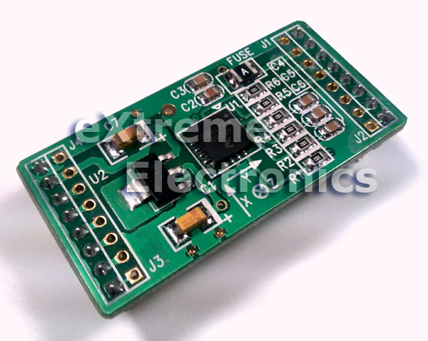
The MMA7260QT Based Accelerometer Module.
In this tutorial we will learn how to interface a 3axis accelerometer with AVR Microcontroller. The accelerometer which we will use is MMA7260QT from Freescale Semiconductors. Most accelerometer chip (including MMA7260) are available only in very small SMT packages, thus bit hard to work with (unless you can fabricate a PCB for it). To solve this issue we have introduced a PCB Module based on MMA726 to make it easy for most of us to work with. It also has a 3.3v regulator chip built in, so you can easily hook it up with 5v development boards and MCUs. You can buy it from the following links.
- 3-Axis Accelerometer Module – MMA7260 (Indian Customers)
- Triple Axis Accelerometer Breakout – MMA7260Q (Sparkfun for US/ Canada or Worldwide)
- Robokits (About 2 times our price and also DO NOT have 3.3v regulator!)
NOTE: Sparkfun Version is Very basic and does NOT has inbuilt 3.3v regulator, so to interface it with 5v logic you need a LM1117-3.3 chip.
 |
3-Axis Accelerometer Module. |
 |
3-Axis Accelerometer Module. |
PIN OUT
| GND | Ground Supply |
| VDD | 3.3 V OUT |
| Sel2 | G Select Pin2 (See datasheet) |
| Sel1 | G Select Pin1 (See datasheet) |
| X | X axis output (g bias point @ 1.65v) |
| Y | Y axis output (g bias point @ 1.65v) |
| Z | Z axis output (g bias point @ 1.65v) |
| Sleep (Active Low) | Low= Sleep High* = Wake |
| GND | Ground Supply |
| +5v | 5 Volts IN |
| DO | NOT USED |
| DI | NOT USED |
| CLK | NOT USED |
| EN | NOT USED |
| RXD | NOT USED |
| TXD | NOT USED |
The MMA7260 Accelerometer Interface.
The block diagram of the MMA7260 Accelerometer Module is given below.
 |
MMA7260 Accelerometer Module Block Diagram |
The signals on left hand side are the input and on the right side are output. The MMA7260 accelerometer module supports 4 selectable g options.
| g-Select2 | g-Select1 | Range | Sensitivity |
| 0 | 0 | 1.5g | 800mV/g |
| 0 | 1 | 2.0g | 600mV/g |
| 1 | 0 | 4.0g | 300mV/g |
| 1 | 1 | 6.0g | 200mV/g |
To select any g Range, simply apply proper logic at the g-Select Pins. You can use the 3.3V out pin to get logic high. Note: Never apply 5v as logic high as it will damage the chip. In this example we will use the first mode, i.e. 1.5g so we leave the g-Select Pins unconnected. The internal PULL DOWN resistors will make both pins logic 0.
For Normal operation the SLEEP pin must be at HIGH logic, so tie it up to the 3.3v Out pin.
Output of MMA7260 accelerometer module.
The output of any axis is an analog voltage proportional to the acceleration in that axis. As the acceleration can be positive, negative or zero. So the output has a zero bias point. That means the output is held at this point for zero acceleration. A negative acceleration will result in voltage less than the zero g point. Normally this zero bias point is half of the supply voltage for mma7260. In our case it is 3.3V so zero bias point is 1.65V.
This is illustrated with the help of following example.
 |
Y axis output. |
In CASE#1
The acceleration due to gravity is in the direction of Y axis so the output is positive hence voltage greater than 1.65V
In CASE#2
The device is inverted, now the acceleration due to gravity is opposite to the Y axis hence a negative acceleration or a Value which is less than 1.65v
If the device is made to lie flat so that Y axis is perpendicular to earths gravitational field then the output will be close to 1.65v
Interfacing Accelerometer with AVR Microcontrollers
Interfacing the module is fairly easy, you just need to connect the X,Y,Z output to the ADC input channels. The inbuilt ADC will convert the analog voltage into a digital number. It is recommended you try out basic AVR ADC programming as described in this tutorial.
After reading the above tutorial you know that AVR ADC will give us a number between 0-1023 for voltage between 0-5V. The relation between adc_value and input voltage is.
Vin=(adc_value/1023)x5
Using the above relation we get the adc_value for zero g point, i.e. 1.65v
Using simple math we get adc_value=337.59 for Vin=1.65
Rounding Up we get adc_value=338 for zero g point.
So we now know that if ADC readings are less than 338 it means negative value. So we subtract 338 from the value provided by the ADC to get the actual acceleration in that direction.
int x; 		//Acceleration in x direction
x=ReadADC(0);	//Read Analog Channel 0 (connected to X output)
x=x-338; 		//Actual Acceleration with sign!
We will write a small demo app that will run on ATmega32 AVR Microcontroller that will read accelerometer data and present it in a 16×2 LCD Module. User is recommended to see the LCD Interfacing tutorial for AVR using the following link.
Those who are using xBoard v2.0 will like to read the following page.
The AVR Must be clocked at 16MHz to run the demo supplied in this page. If you are using a brand new chip don’t forget to change the Fuse Bits to following value.
- HIGH Fuse Byte = 0xC9
- LOW Fuse Byte = 0xFF
The above setting will disable JTAG and switch to external crystal. Before doing so please solder a crystal of 16MHz to the XTAL pins.
Hardware Setup for Testing 3-Axis Accelerometers with AVR
You can make a small circuit as shown in the schematic below. Otherwise you may use one of our ready made development boards. If you cannot get the expected result with home made circuit then it is suggested that you purchase a development board to ease your life.
 |
Schematic for AVR ATmega32 and LCD Connection. |
Use a 5v supply system using LM7805 to power both the accelerometer and the above circuit. Connect Accelerometers Xout to ADC0, Yout to ADC1, Zout to ADC2 respectively. Connect Accelerometers SLEEP pin to 3.3v out from the accelerometer module. Leave both the g-Select pins unconnected. Now you are ready to run the demo program.
If you are using the xBoard v2.0 then you don’t need to built any circuit. Just hookup the LCD Module as shown below.
 |
A 16×2 Character Alphanumeric LCD Module Supplied with xBoard |
 |
A 12 PIN Connector is already soldered to the LCD Module |
 |
12 PIN Header For LCD Module Connection on xBoard. |
 |
LCD Module Connected. |
 |
The Whole Setup. |
Use the extra 5v out and GND pins to supply the accelerometer module. Then connect X,Y and Z out pins from accelerometer to the xBoard’s Analog in pins(ADC0,ADC1,ADC2 etc). The location all these pins is show below.
 |
PORTA/ADC Port |
avr-gcc program to test Accelerometer Module.
The following program reads the acceleration in 3 axis of the accelerometer module and displays the result on 16×2 lcd module. The program is written in C language and compiled using avr-gcc compiler using the AVR Studio Development Environment. These tools must be installed correctly and user must have basic knowledge of usage. If you are new to them please read the following tutorials.
User is assumed to have basic knowledge of C language and programming concepts. Teaching basic programming techniques (like loops or control statements) is NOT in the scope of our tutorial series. We focus only on programming embedded system and closely related techniques for people who already know what is programming. If you are new to programming (or C) itself then jumping into system programming is NOT for you. Go learn programming is an environment that is more suited for beginner, like a PC or MAC. You may first get started with simple languages like LOGO (for Kids) or BASIC, then move to professional languages like C/C++ or Java.
/*********************************************************************

                 xBoard(TM) v2.0 Sample Programs

               ------------------------------------


Description :  Demonstrate the use of Accelerometer to sense tilt angle.
            Shows the raw X,Y,Z readings on LCD Disp.

Accelerometer: MMA7260 - 3 axis accelerometer breakout board.

Author      : Avinash Gupta

Web         : www.eXtremeElectronics.co.in


            Copyright 2008-2010 eXtreme Electronics, India

**********************************************************************/

#include <avr/io.h>
#include <util/delay.h>


#include "lcd.h"

/*

Function To initialize the on-chip ADC

*/
void InitADC()
{
   ADMUX=(1<<REFS0);                                     // For Aref=AVcc;
   ADCSRA=(1<<ADEN)|(1<<ADPS2)|(1<<ADPS1)|(1<<ADPS0);    //Rrescalar div factor =128

}

/*

Function to read required analog channel and returns the value

Argument:
   Channel number from 0-7

Return Vale:
   Result of conversion on selected channel

   ranges from 0-1023

*/
uint16_t ReadADC(uint8_t ch)
{
   //Select ADC Channel ch must be 0-7
   ch=ch&0b00000111;
   ADMUX&=0b11100000;
   ADMUX|=ch;

   //Start Single conversion

   ADCSRA|=(1<<ADSC);

   //Wait for conversion to complete
   while(!(ADCSRA & (1<<ADIF)));

   //Clear ADIF by writing one to it

   //Note you may be wondering why we have write one to clear it

   //This is standard way of clearing bits in io as said in datasheets.
   //The code writes '1' but it result in setting bit to '0' !!!

   ADCSRA|=(1<<ADIF);

   return(ADC);
}

/*

Simple Delay function

*/
void Wait(uint8_t t)
{
   uint8_t i;
   for(i=0;i<t;i++)
      _delay_loop_2(0);
}


void main()
{
   int16_t x,y,z; //X,Y,Z axis values from accelerometer.

   //Wait for LCD to Startup
   _delay_loop_2(0);

   //Initialize LCD, cusror style = NONE(No Cursor)
   LCDInit(LS_NONE);
   LCDClear();

   //Initialize ADC
   InitADC();

   //Put some intro text into LCD

      LCDWriteString("  Accelerometer ");
      LCDWriteStringXY(0,1,"      Test      ");
      Wait(150);

   LCDClear();
      LCDWriteString("     eXtreme ");
      LCDWriteStringXY(0,1,"   Electronics  ");
   Wait(150);

   LCDClear();

   while(1)
   {
         x=ReadADC(0);           // Read Analog value from channel-0

      y=ReadADC(1);           // Read Analog value from channel-1
      z=ReadADC(2);           // Read Analog value from channel-2

       //Make it signed value (zero point is at 338)
      x=x-338;
      y=y-338;
      z=z-338;

      //Print it!

      LCDWriteStringXY(0,0,"X=");
      LCDWriteInt(x,4);

      LCDWriteString(" Y=");
      LCDWriteInt(y,4);

      LCDWriteStringXY(0,1,"Z=");
      LCDWriteInt(z,4);

      Wait(20);


   }


}
Downloads
- AVR Studio Project for MMA7260 based accelerometer module test (For ATmega32)
- HEX File for MMA7260 based accelerometer module test (For ATmega32)
What’s Next?
By
Avinash Gupta
Facebook,
Follow on Twitter.
www.AvinashGupta.com
me@avinashgupta.com
Good work bro.!!
i am very happy to have this at your stores..for damn low price…but pcb looks some what bigger in size..
will soon buy one from you..
thanks a million times..
nice work ,
all your tutorials are very helpful.
i will buy this module as soon as i get some extra cash.
Hello Avinash,
Your tutorials are the basis of every experiment I undertake. The xBoards that I bought were really of good quality and are the lowest priced in the complete embedded market. However, I have a suggestion about your online store.I request you to put up some plug in modules like Regulated 5v power and motor drivers too. Also, I would like to see matrix keypads and joysticks.As your website has turned into a haven for beginners, I request you to keep up this good work of providing quality tutorials, God bless you.
@Victor
Thanks!!!
I already have Joystics (Both analog and digital) and Keypads Imported and lying in the warehouse. Will be show cased soon in the Webstore.
Hello Sir,
I am MANU from Kerala. I have read your tutorial interfacing Accelerometers with microcontrollers. It’s very interesting and after reading I decided to check it. With the help of am friend I got an accelerometer. But that was little different from the one that you have used in the tutorial. In my accelerometer there were only 5 pins.
1–+VCC
2-GND
3—INT
4—SDA
5-SCL
When I searched in the web about this ,I came to know that this type of sensor can be interfaced with micro controllers using I2C protocol. I have no idea about I2C protocol & when I searched in the web about this some links has shown. But none of us provided me with sufficient information to use ma accelerometer with MCU. So I humbly request you to help me in this situation by telling me how to interface ma sensor with MCU.I have already sent an mail previously to you asking about a doubt but you have not replied for it. I think you might have not noticed it. So please help me in this situation. Waiting for your reply..My mail id is mjklives@gmail.com… The accelerometer I gt is this one
http://www.rhydolabz.com/index.php?main_page=product_info&cPath=137_138&products_id=323
@Manu,
You buy from rhydolabz, pay them, make them rich and come to us for free help? Why don’t you ask rhydolabz to give you the guidance? I don’t know why you buy from store that give no documentation, no source code and no example (like rhydolabz)???
Until now you should have realize than quality support is more important than the product itself!
WE STRICTLY DO NOT SUPPORT OTHER INDIAN VENDOR PRODUCTS, SO DON’T ASK ABOUT THEM IN OUR SITE!
While you are free to ask anything you buy from non Indian Sites like Adafruit, SFE etc
I didnt buy from them…its ma frnd who bought it from them an year ago..bt he cant able to make use of it.So when he heard that i am planning to buy an accelerometer he said me tht he hd one & gave that to me.I had no intension to make them rich.Why should i buy items from other places when EXTREME ELECTRONICS is providing them at the lowest price that no one else can provide.Thats why i bought the burners,Development board,sensors etc from you and started learning MCU programming.And within 3 weeks i can say that i studied well abt MCU programming .I am doing ma B-tech in mechanical engineering and now i knw MCU programming.Even ECE students in ma college didnt know well abt MCU programming.All the credits for it goes to you MR.AVINASH..because without your tutorials and examples i cant able to reach up to a level like this. Now this case…. i have seen interfacing DS1307 chip with microcontroller in one of your tutorials and i happen to see i2c protocol used in that..thats y i askd you to help me ..as you know the cost of sensor is nearly 900/-..i am student & i cant have sufficent money to buy them from you at present.With the money i hd i bought burners,developments,sensors etc from you.so when i gt tht accelerometer free from ma friend i didnt thnk f anything else.I think you may understand y i used the accelelrometr from rhydolabz…if you can help me in this situation plz help me.whats all i ma doing for this is due to my passion in electronics world..plz understand me..
@Manu
To use those sensor you need to learn I2C which is again a very well designed communication protocol. You need in-depth knowledge of I2C protocol. The I2C specs are available from Philips Semi(now NXP) they are long, but you have to read them. Then go to the datasheet of the MCU and read the I2C peripheral details (in AVRs it is called TWI due to copyright reasons). Then write basic I2C routines. Finnaly go to the datasheet of the Accelerometer of and see how it exchange data. Thats it!!!
thnk you for your reply..i have read those datasheets bt cant able to understand them all..anyway i thnk its better to use MMA7260QT than the one with me.so will buy it as soon as i can…
I have read your tutorial interfacing Accelerometers with microcontrollers, and it’s very cool. but i nees source code in CodeVision AVR…! can u give me source code in CodeVision AVR? Please thank’s
@Pengedar Cangcut
No. I work with avr-gcc only.
Sir,
Its very nice to see this tutorial. It very helpful to begin with thanks a lot. but I have one doubt that the data sheet says that arcsin of the calculated value is neccesary to calculate the tilt. Can you update the code for calculating tilt angle from these ADC values? Thank you.
Sir,
I wanted to know that if i get MMA7260q in India then can i directly give the vdd pin 5V or i will have to convert it to 3.3V dc ? if yes then which regulator shall i use for the same ? thank u
Hello Sir,
I have read your tutorial interfacing Accelerometers with microcontrollers.It’s very interesting. I am using Adxl335 Accelerometers and the purpose, I am using is to determine the angle movements of X,y And Z , my current task is to determine the ranges voltage of each axis and my question is ”
1. Can i use this sensor to calculate the angle movements X,y,Z to get from 0 -360 degree?
2. if i want to determine the voltage of each axis which method i can use ? i am looking for your reply thanks
hello avinash!
your tutorials are amazing and this website is extremely marvelous!
how can we simulate MMA7260 in proteus (ISIS) professional or any other simulator?
i did not find any file or any other type of acce sensor like ADXL330 in proteus!
is there any way we can simulate accelerometer?
Your product is the best i could find on the web. But it is not in stock. could you recommend some other website from which i could get a similar board
Pingback: What type of sensor???
Article is well made.
I made by myself good project with accelerometer
http://www.youtube.com/watch?v=JM7N1M8oMmY&feature=plcp
Hi Avinash sir,
My self Sachin i am in finer year of B.E. i am work on project i.e. ‘automatic robotic arm base on mems’ i need an help regarding info about principal operation of MMA7260 and its inter facing with atmega 32
in detail.
I read your articles , so i think u able help me. please reply me
So what is written in the Article above ?
Sir,
I want your help regarding USBasp the burner can i get your mail id…
Regards
Ismail
hello sir
when the accellerometer is stationary, whats the output then?? cuz stationary objects has no accln so the output shud be mid point. is it so??
somebody told me that it shows the value according last experienced acceleration so i got confused. so asked you!
@Jaspreet Singh,
These accelerometers will show 0 acceleration when not being accelerated. Just one point in the axis along earth gravitational force it shows acceleration relative to earths gravitational acceleration. That means 0 acceleration is actually reported as 9.8 m/s^2
Hi,
Can we see the accelerometer output directly on oscilloscope and measure the acceleration,For eg:- in the case of shake tables.
Yes you can.
Is it possible to sense the angle of a rotary machine by this accelerometer.
Hi avinash,
I am Sam doing 2nd year B. TECH. I bought all the stuff required from here only and your tutorial is excellent and it works awesome now i am trying to make a tilt sensing system where the display must show the angle in degrees with respect to the ground ,So can you please try posting the code for that or could you please tell the procedure or modifications and formula to be used. I shall be very much grateful for our help.
@Samloyd,
“I bought all the stuff required from here only”
what does this mean?
Sir,
Firstly i apologize for for refering you by your name instead of sir as i m younger to you and secondly what i meant was i had purchased the hardware required for this system from extreme electronics. I did not mean to offend anyone and if it has offended you i again apologize for that. Now i hav got a doubt on how to get to display the analog values from any sensor on an lcd. And thanks in advance.
@Samloyad,
No need to address me by calling sir, its okay to call by name.
Please refer which development board you are using, so that we can supply suitable firmware.
Sir,
It is the same xboard v2.0 with LCD module and USB AVR programmer. And my other doubt is how to get to display the analog values of that sensor output on to LCD
Example to show ADC data on LCD screen is clearly shown in the documentation!
http://xboard.extremeelectronics.co.in/ADC.htm
use simple trigonometry for the calculations! Hope you have passed 8th std.
Sir,
thank you very much my doubts are all cleared. And this forum is really great.
hello avinash…!can u please send me the functions written in lcd.h header file..?or if possible the complete code
@Saheba,
Did you try the first link in the download section?
yes i have attached the lcd.h and myutils.h to the main program, but its showing the the following functions are undeclared..
void LCDInit(uint8_t style);
void LCDWriteString(const char *msg);
void LCDWriteInt(int32_t val,unsigned int field_length);
void LCDGotoXY(uint8_t x,uint8_t y);
void LCDByte(uint8_t,uint8_t);
so please u can send the fuction definitions for the fuctions in lcd.h header file…..
Hello Avinash,
I’m working on project “Air mouse” sensing the hand movement using accelerometer
sensor which gives acceleration values in x,y,& z direction.
These analog values will be converted into digital form and then transmitting
the same using bluetooth module to computer for cursor movement.
Here I need help to interface bluetooth(WRL1300) module with
ATMEGA32(microcontroller). please give any suggestions..
Thank you..
hello avinash!
please reply its very urgent……
thank you
@Saheba,
Sorry, I don’t get much free time.
Pingback: Accelerometer, Gyroscope and IMU Sensors - Tutorials - Into Robotics
Pingback: Using the Analog To Digital Converter.
can digital accelerometer(MMA7660 i.e., i2c out put) can be used in wireless technology i just need the answer yes or no……
can this be used in fsae sars
Pingback: Datasheet For Mma8452q Triple Axis Accelerometer Games | Xtreme MMA Training
I want to enable free fall condition. How should I do code for it? Please if anybody have code then provide
Can any help me to get adsl345 library for proteus because I wan to run simulation with it in my project
Pingback: Three Axis Low-g Accelerometer Sensor with Arduino UNO - ElectronicsDNA