Seven segment displays are very common for electronic product to display numerical output. Many common devices like calculators, watches, electronic weighing scales,ovens etc use them. You must have also seen lifts display the current floor numbers in seven segment displays. So in this article I will show you how to use 7-Segment displays in your own projects.
Fundamentals
A seven-segment display is so named because it is divided into seven different segments that can be switched on or off. The different combination of these segments switched on produces different English numbers. The display also has a decimal point.
 |
Fig: Seven Segment Display |
 |
Fig: ‘4’ |
The figure shows a seven segment display and the names of the various segments. For example if you want to display number 4 then segments that will be ‘on’ are {f,g,b,c} while rest are ‘off’.Basically the seven segments are just LEDs. The one common end of all the leds are connected while the rest are available. Depending on whether anode or cathode of all the leds are common they are of two types.
1) Common anode 2)Common cathode
 |
Fig: Common Cathode Type |
 |
Fig: Common Anode Type |
PIN Configuration
Now you know the basic of these displays, to use them you should know the pin configuration of the commercially available displays. As you must have guessed these displays should have nine pin( one for each segment + decimal point +common) but the available modules have two pins for common. They are internally connected. So they have total of 10 PINs.
 |
Fig: Pin Configuration |
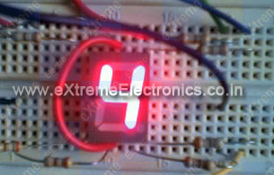 |
Fig: A seven segment display |
Interfacing with MCU
Interfacing these displays are same as interfacing LEDs with MCU. You need 7 MCU port pins to control them. If you also want to control the decimal point you need one extra pin. The connection is simple.
 |
Fig: Connection with MCU |
Here I have interfaced a common anode(+) 7 segment display with PORTD of AVR.If you have made the “home made avr dev board” then you can easily connect this to PORTD of the board by using 8PINconnectors. The segments will be "on" when levels on the PORT is low, that is 0.
Programming
These displays are very easy to program in C. I am giving here a function, which you may use to display digits in 7-segment display. The sample program uses the function to continuously display digits from 0-9 and then repeating the sequence.
/*

A program to demonstrate the use of seven segment displays.

Hardware:
A single seven segment display connected to PORTD as

a->PD7
b->PD6
c->PD5
d->PD4

e->PD3
f->PD2
g->PD1
DP->PD0

By:
Avinash Gupta

eXtremeElectronics.co.in
avinash@extremeelectronics.co.in

*/

#include <avr/io.h>
#include <util/delay.h>

//Configurations

//**************
// Here you may cange the port in which you have connected the display
#define SEVEN_SEGMENT_PORT PORTD
#define SEVEN_SEGMENT_DDR DDRD


void SevenSegment(uint8_t n,uint8_t dp)
{
/*
This function writes a digit given by n to the display

the decimal point is displayed if dp=1

Note:
n must be less than 9
*/
   if(n<10)
   {
      switch (n)
      {
         case 0:
         SEVEN_SEGMENT_PORT=0b00000011;
         break;

         case 1:
         SEVEN_SEGMENT_PORT=0b10011111;
         break;

         case 2:
         SEVEN_SEGMENT_PORT=0b00100101;
         break;

         case 3:
         SEVEN_SEGMENT_PORT=0b00001101;
         break;

         case 4:
         SEVEN_SEGMENT_PORT=0b10011001;
         break;

         case 5:
         SEVEN_SEGMENT_PORT=0b01001001;
         break;

         case 6:
         SEVEN_SEGMENT_PORT=0b01000001;
         break;

         case 7:
         SEVEN_SEGMENT_PORT=0b00011111;
         break;

         case 8:
         SEVEN_SEGMENT_PORT=0b00000001;
         break;

         case 9:
         SEVEN_SEGMENT_PORT=0b00001001;
         break;
      }
      if(dp)
      {
         //if decimal point should be displayed

         //make 0th bit Low
         SEVEN_SEGMENT_PORT&=0b11111110;
      }
   }
   else
   {
      //This symbol on display tells that n was greater than 9
      //so display can't handle it

      SEVEN_SEGMENT_PORT=0b11111101;
   }
}


void Wait()
{
// An approx one second delay for  12Mhz CPU clock
   uint8_t i;
   for(i=0;i<46;i++)
   {
      _delay_loop_2(0);
   }
}


void main()
{
   //Setup
   SEVEN_SEGMENT_DDR=0xFF;    //All output
   SEVEN_SEGMENT_PORT=0xFF;   //All segments off

   uint8_t count=0;

   while(1)
   {
      SevenSegment(count,0);

      count++;
      if(count==10)
      {
         count=0;
      }

      Wait();
   }
}
Downloads
What’s next ?
- Drive more displays with less i/o pins, go learn Multiplexing technique!
- Display room temperature on seven segment display
- Make a digital stop watch.
Download PDF version | Get Adobe Reader Free !!!
Pingback: Multiplexed Seven Segment Displays. | eXtreme Electronics
Pingback: Interfacing Temperature Sensor with AVR Microcontrollers - LM35 | eXtreme Electronics
hi avinash,
cud u plz tell me about unit8_t.i ve not come across such a datatype..
thanks in advance..
Hello Dhanya,
As a beginner you have used int & char. But in any professional c / c++ programming they are not used directly because the size depends on OS/Platform and implementation of C/C++. So every where in real programming senario you have “typedef” for data types. For example development of Windows application with SDK uses its own typedefs. Almost every tool/library provide typedefs.
So when you are in real c/c++ development you always come across new data types, so don’t be afraid.
Now your question-> What is uint8_t?
Ans: It is a 8 bit unsigned integer. Similarly there are uint16_t and int8_t and int16_t. The prefix u tells that it is unsigned i.e. it can hold only positive value.
See
http://www.nongnu.org/avr-libc/user-manual/stdint_8h.html
So
every where in your program where you are specifying uint16_t you are EXACTLY demanding that you need a int with 16bits and which is UNSIGNED. When you compile it under AVR with GCC it will automatically get translated to “unsigned int” (which is a basic C data type). Since int under avr-gcc is 16bit wide.
And suppose you move some code (say bubble sort) from AVR to ARM platform (or even Windows) then you if you had written “unsigned int” they would all have become 32 bit wide !!!
So now you just need to change a singe defination of uint16_t and every place of your code that used uint16_t will get correctly defined !
Hope you should have got it. 🙂
So
uint8_t is not a new data type that you may be thinking that you missed while learing C. Its just a method for writing a more manageable code, the professional way.
Hello Sir,
May you please explain the following
for(i=0;i<46;i++)
{
_delay_loop_2(0);
}
Atleast I understood that 46 refers to 1 second and 23 refers to 0.5 second but how does that work or I mean to say What is the meaning of the expression inside the loop.
Hello Prafull,
The _delay_loop_2(0) is a 16bit delay counter that means it can count up to 2^16 i.e. upto 65536. And in one loop it burns 4 cpu cycle. We have pass 0 to count to maximum i.e. 65536
Since we are using 12MHz CPU the time period for
1 cycle = 0.000000083 sec
4 cycle = 0.00000033 sec
4x 65536 = 0.22sec
so 46 x 0.022 sec = 1.012 sec
that is approx 1 sec.
dear sir,
could you pls provide information how to inteface a loadcell with atmega8 and sample code in c my aim is to display the weight in 16×2 lcd if possibl pls provide circut
Hey, Just a quick question. How would you change the delay? The way you have the delay set up is a bit different from what I’m use to. When I change the _delay_loop_2(0); It is much longer than one second. About 5 seconds. Please share your thoughts.
BTW your tuts are amazing! I wish I saw them earlier.
@David
Please note TIMING depends on CPU speed. I clearly said it is for 12Mhz external crystal.
In this example timing didn’t matter much but in complex examples what you can get is black LCD screens (instead of an intended message) or no response to remote control signals, no resonse to data transfer. Because timming realy matters in those case!!!
Pingback: Interfacing LCD Modules with PIC Microcontrollers. | eXtreme Electronics
Design a seven segment display which displays “INDIA IS GREAT “with certain delay (say 5 sec) between successive letter displays in continuously……….
………..
HELP ME PLEASE ITS URGENT
hey saurabh,7 segment display is used for displaying numbers and not alphabets.coz u cant display “N” and “T” if i am right….
there are displays available in which we can print letters like “v”
use a 16 segment display buddy..
or else go with a simple 16×2 lcd display!!
Thank you so much. This article helped me a lot.
thanks for your commitment.I appreciate your job to publish these informations about pic with 7 seg.wish u all the best.
thank you sir .the inormation in this article helped me a lot.
thank you sir,this article has helped me a lot
Well, I couldn’t understand the followings lines:
SEVEN_SEGMENT_DDR=0xFF; //All output
SEVEN_SEGMENT_PORT=0xFF; //All segments off
I mean, we can use DDRD or PORTD, but what’s the logic behind using SEVEN_SEGMENT before them?? Is this some kind of macro?
Thanks…
Mayank Prasad
@Mayan
So that user can change the port assignment for displays easily !!!
If some one wants the disp on PORTA, he/she just need to change that in one place.
This process is called configuration.
If a program is really bit and complex, we have a separate config.h file.
So the user just need to open up the config.h file change the required options and Voilla the program is now ported for the new platform !!!
If the program is really really big. Then we supply a windows GUI software for editing the configuration file. So now the user just need to fire the GUI find a selection area for display, use the drop down box to simply select the seven segment port of his/her choise !!! If you have changed windows wallpaper or changed the rigtone of your mobile you must be know what ease these GUI provide!
hi,
could you please help me in coding the program to interface 4-digit 7 segment display using pic16f877a using mplab IDE software…
weahhhhh
Thank you!! It helped me a lot!!
i did not get the fact that to light up a segment we need to give logical low.why not high as in most cases
@Vishwanath
because the display is CA (or common anode) so the segments are Cathode (-) of the LEDs and the common is Anode (+). So lit a segment we need to ground them that is why we put 0 (or GND) to the segment.
Dear Sir,
I need alfanumeric display 2″ & Seven sigment Display1/2″
Regards
Ajit Kumar
09958816356
Pingback: connecting microcontroller to seven segment led..??
Pingback: seven segment display operation
Ho gya ji
ho gyaaaa………
TANKHU JI
hey avinash,
what will the frequency @ base of each transistor?
if there is 3 transistor 3Hz?
Pingback: Simple decimal counter using ATMEGA16 "code c"
sir,
plz suggest me some tutorial of basic AVR programming. I dnt knw how to programming
thank you
@Inderjeet The best tutorial of AVR PROGRAMMING is datasheet of the AVR.
thnx for reply.i agree with you bt i dont knw how to use ‘uint16_t’,other function
Hi,
Ive followed tutorial, but when segments are off, they are not fully off, the are just dim . and it is therefore really hard to read, what have i done wrong?
Possible reason for this is the fact that when u are turning an atmega pin high then its not giving voltage as high as vcc..
say vcc is exact 5, and when u are turning a certain pin of atmega as high you are getting 3.8-4 volts only then theortically we expect a zero potential difference which should result in turning off 7 segment completely, but in practical we still have ~1 volt potential difference, which leads to what you call as DIMMING of seven segment
hello sir,
why use _delay_loop_2(0) when a simpler version _delay_ms() is available?
is there any particular advantage to using the former?
i am using renesas r5f21246sn.it has 20Mhz crystal frequency.the problem now i am facing is when program was in display function it diplay current temp . if the program execution is in adc module that time display l=will not be there . but i want to display continuosly changing temperature continuosly……please help me
hi, avinash
pdf format of all project are not available..can you help me with that.
thank u.