By interfacing different types of sensors with our MCU we can sense the environment and take decisions, in this way we can create "smart" applications. There are wide variety of sensors available. In this tutorial we will learn about a popular sensor LM35 which is precision centigrade temperature sensor. It can be used to measure temperature with accuracy of 0.5 degree centigrade. We can interface it easily with AVR MCUs and can create thermometers, temperature controller, fire alarms etc.
Things Required
| S. No. | Item | Image |
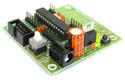
| 1 |
Contains the core AVR circuit including 5v regulator, reset, ISP. |
 |
| 2 | Four common anode displays multiplexed with driver transistors and current limiting resistors. |
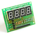 |
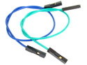
| 3 | Single Pin Female to Female Burg Wires Used to interconnect the two boards. And the sensor.
|
 |
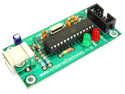
| 4 |
To upload the program to the development board. |
 |
| 5 | LM35 Temperature Sensor | 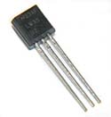 |
LM35
LM35 by National Semiconductor is a popular and low cost temperature sensor. It is also easily available. You can buy one from here online. It has three pins as follows.
 |
Fig – LM35 Pin Configuration |
|
The Vcc can be from 4V to 20V as specified by the datasheet. To use the sensor simply connect the Vcc to 5V ,GND to Ground and the Out to one of the ADC (analog to digital converter channel). The output linearly varies with temperature. The output is
10MilliVolts per degree centigrade.
So if the output is 310 mV then temperature is 31 degree C. To make this project you should be familiar with the ADC of AVRs and also using seven segment displays. Please refer to following articles.
- Using the ADC of AVRs
- Using Seven Segment Displays.
- Using Seven Segment Displays in Multiplexed Mode.
The resolution of AVRs ADC is 10bit and for reference voltage we are using 5V so the resolution in terms of voltage is
5/1024 = 5mV approximatly
So if ADC’s result corresponds to 5mV i.e. if ADC reading is 10 it means
10 x 5mV = 50mV
You can get read the value of any ADC channel using the function
ReadADC(ch);
Where ch is channel number (0-5) in case of ATmega8. If you have connected the LM35’s out put to ADC channel 0 then call
adc_value = ReadADC(0)
this will store the current ADC reading in variable adc_value. The data type of adc_value should be int as ADC value can range from 0-1023.
As we saw ADC results are in factor of 5mV and for 1 degree C the output of LM35 is 10mV, So 2 units of ADC = 1 degree.
So to get the temperature we divide the adc_value by two
temperature = adc_value/2;
Finally you can display this value in either the 7 segment displays by using the Print() function we developed in last tutorial or you can display it in LCD Module. To know how to display integer in 7 segment displays and LCD Modules see the articles.
In this tutorial I have used four 7 segment displays to show the temperature.
Program (AVR GCC)
/*

Description:   Program to demonstrate the use of LM35
            Temperature Sensor.

            The temperature is display on seven
            segment display.
________________________________________________________

Author:     Avinash Gupta
Date:    14 Dec. 2012
Updated:
Web:     www.eXtremeElectronics.co.in


*/

#include <avr/io.h>
#include <avr/interrupt.h>
#include <util/delay_basic.h>


#define SEVEN_SEGMENT_PORT PORTD
#define SEVEN_SEGMENT_DDR  DDRD

volatile uint8_t digits[3];

void SevenSegment(uint8_t n,uint8_t dp)
{
/*
This function writes a digits given by n to the display
the decimal point is displayed if dp=1

Note:

n must be less than 9
*/
   if(n<10)
   {
      switch (n)
      {
         case 0:
                          //.gfedcba
         SEVEN_SEGMENT_PORT=0b00111111;
         break;

         case 1:
                        //.gfedcba
         SEVEN_SEGMENT_PORT=0b00000110;
         break;

         case 2:
                        //.gfedcba
         SEVEN_SEGMENT_PORT=0b01011011;
         break;

         case 3:
                        //.gfedcba
         SEVEN_SEGMENT_PORT=0b01001111;
         break;

         case 4:
                        //.gfedcba
         SEVEN_SEGMENT_PORT=0b01100110;
         break;

         case 5:
                        //.gfedcba
         SEVEN_SEGMENT_PORT=0b01101101;
         break;

         case 6:
                        //.gfedcba
         SEVEN_SEGMENT_PORT=0b01111101;
         break;

         case 7:
                        //.gfedcba
         SEVEN_SEGMENT_PORT=0b00000111;
         break;

         case 8:
                        //.gfedcba
         SEVEN_SEGMENT_PORT=0b01111111;
         break;

         case 9:
                        //.gfedcba
         SEVEN_SEGMENT_PORT=0b01101111;
         break;
      }
      if(dp)
      {
         //if decimal point should be displayed

         //make 7th bit high
         SEVEN_SEGMENT_PORT|=0b10000000;
      }
   }
   else
   {
      //This symbol on display tells that n was greater than 9
      //so display can't handle it

      SEVEN_SEGMENT_PORT=0b11111101;
   }
}

void Wait()
{
   uint8_t i;
   for(i=0;i<10;i++)
   {
      _delay_loop_2(0);
   }
}

void Print(uint16_t num)
{
   /*


   This function breaks apart a given integer into separate digits
   and writes them to the display array i.e. digits[]

   */
   uint8_t i=0;
   uint8_t j;

   if(num>9999) return;


   while(num)
   {
      digits[i]=num%10;
      i++;

      num=num/10;
   }
   for(j=i;j<4;j++) digits[j]=0;
}


void InitADC()
{
   ADMUX=(1<<REFS0);// For Aref=AVcc;
   ADCSRA=(1<<ADEN)|(7<<ADPS0);
}

uint16_t ReadADC(uint8_t ch)
{
   //Select ADC Channel ch must be 0-7
   ch=ch&0b00000111;
   ADMUX|=ch;

   //Start Single conversion

   ADCSRA|=(1<<ADSC);

   //Wait for conversion to complete
   while(!(ADCSRA & (1<<ADIF)));

   //Clear ADIF by writing one to it
   ADCSRA|=(1<<ADIF);

   return(ADC);
}

void main()
{
   uint16_t adc_value;
   uint8_t t;

   // Prescaler = FCPU/1024
   TCCR0|=(1<<CS02);

   //Enable Overflow Interrupt Enable
   TIMSK|=(1<<TOIE0);

   //Initialize Counter

   TCNT0=0;

   //Port B[3,2,1,0] as out put
   DDRB|=0b00001111;

   PORTB=0b00000001;

   //Port D
   SEVEN_SEGMENT_DDR=0XFF;

   //Turn off all segments
   SEVEN_SEGMENT_PORT=0X00;

   //Enable Global Interrupts
   sei();

   //Enable ADC
   InitADC();

   //Infinite loop
   while(1)
   {
      //Read ADC

      adc_value=ReadADC(0);

      //Convert to degree Centrigrade
      t=adc_value/2;

      //Print to display
      Print(t);

      //Wait some time
      Wait();

   }
}

ISR(TIMER0_OVF_vect)
{
   /*

   This interrupt service routine (ISR)
   Updates the displays

   */
   static uint8_t i=0;

   if(i==3)
   {
      //If on last display then come
      //back to first.
      i=0;
   }
   else
   {
      //Goto Next display
      i++;
   }

   //Activate a display according to i
   PORTB&=(0b11110000);
   PORTB|=(1<<i);

   //Write the digit[i] in the ith display.
   SevenSegment(digits[i],0);
}
Hardware
The hardware of the project is simple you first make the last project (Multiplexed Seven Segment Displays) and then add the LM35 as stated above. Connect output pin of LM35 to ADC0 (PIN 23) of ATmega8.
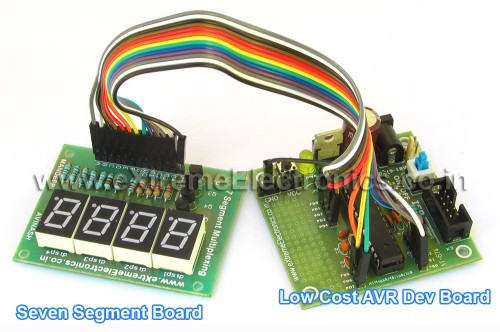 |
Fig. LM35 Temperature Sensor Demo |
Hello Gupta,
I’m a beginner with AVRs, so great thanks for the very useful series!
As I see the LM35 provides -1V to +6V representing the temperature. What is the best practice in this case to convert negative voltages with ADC? Here in Hungary now we have less than -15°C at night :))
Thanks in advance!
Zsolt
@Zsolt
Hello.)
In response to your question i have posted a topic in forum, see it for answers.
http://forum.extremeelectronics.co.in/viewtopic.php?f=2&t=29
🙂
I have a question?
May I have PCB & diagram of this project.
cas I’m not sure about the circuit!!!!!
Hello Avinash
Do you have any tutorials to send AT commands via C program
hi i m a student of third yr electonics i have recetly made a project using LM35.The name of project is temperature sensor i jst wanted to know what r the advantages of this project and application areas where i can use this project pratically
Hello Monika,
Are u talking abt the above project or u got it from some where else?
Your question seems to be too academic !
🙂
Well Digital Temperature sensors are used every where, from monitoring CPU temperature in PC to Space stations !!!
Also in modern refrigerators and Ovens. 🙂
Hi avinash,
i tried the above code on my board by deccan robots.When the program is burned its showing b.b.b .I am not able to trace what the problem is.I am using atmega16 Mcu.I have connected lm35 to pin0 of portA,data lines of portD to seven segment display,and portC [2,1,0]to display control lines.Kindly tell what is the problem?Also can u explain what happens once the adc values are read?
I will explain what i have understood.Once print (t)is executed,it will go to that subroutine and check if no is less than 999 or not.If yes it will calculate digits[o]=(suppose)255%10=5 and num=25,now i will be incremented by 1.After this digits[j]=digits[0]=0. Now it will go to timer overflow rotine and and display the digit by using SevenSegment(digits[i],0);mean while next display is also detected.But i am not able to find out why u have used digits[j].Please explain me?
hiii avinash,
in this ADC conversion u have sex REFERENCE voltage to AVcc i.e REFS0 as 1, and REFS1 as 0, and in the data sheet of ATMEGA8 i have found that, if the reference voltage is set like this, we need to use an oscillator should be connected externally to Aref terminal , is that required? if it is required plzzz tell me from which terminal to terminal v need to connect that oscillator…..thanx for posting all this stuff for us…..
@Teja
It is not OSCILLATOR but an INDUCTOR of 10uH
and YES it is necessary to put that for perfect,clean and noise free performance.
You can find one here
http://shop.extremeelectronics.co.in/product_info.php?cPath=24_31&products_id=55
Hi, Avinash can you just help in the CODE to make ADC conversion at slow speed so that the bits doesn’t fluctute while displaying the LM35 value on the seven segment display
Hi Avinash
pls give mail me the whole circuit connection of the above project(interfacing LM35 and 3 digit LED display with ATMEGA)
Hi avinash
I’m a beginner with AVRs, so great thanks for the very useful series i tried this it works display the temperature but in rotating i want continuous (3 digits SAME time) Where can i to change in program pl help me
@manikandan
This is because the CPU is running slow. Make it fast by attaching an external 16MHz crystal and write FUSE BYTE as high=C9 and low=FF
Hi Avinash,
Thanks for ur kind help… i changed the oscillator as 16MHz and got a stable display with slit blinking… pls guide me where to change the FUSE BYTE.
hi Avinash,
I’m a beginner with AVRs, so great thanks for the very useful series, pls help me how to stop the flickering of LED displays… i hav used 16MHZ externally and the digits are visible to eyes but have some flickering.
Quote
“As we saw ADC results are in factor of 5mV and for 1 degree C the output of LM35 is 10mV, So 2 units of ADC = 1 degree.”
can’t figure out ,how the declaration is made.
can anybody explain me the above declaration taken from the tutorial.
Regards,
-Gaurav Parida
Hey, was just looking through your web site and decided to add the RSS feed, however it’s not working with my webbrowser (I am viewing it with Opera) any kinda way to get around this?
hi Avinash,
i am doing the project using humidity sensor HTF3226 its o/p is in frequency so can u help me to display humidity on lcd
bt how to manage the flickering of the display?pls give details…….otherwise its ok,program is allright.
@Sayantan
To reduce flickering set fuse bit as
Low = ff
High = c9
thnx for your ans,bt can you pls tell me how to set fuse bit low & high as ff & c9 respectively?
ok,now I have reduced the flickering by vanishing the bc557 transistor frm the circuit,and it looks fine without any flickering.But I know that it may be harmfull to mcu to connect
the display directly to the port,as it can make oveload.So I have to put the transistors again in the circuit.Now my question is what is the reason behind that flickering behaviour of transistors,is that for their internal delay or anything else?Still wating for any further assistance to reduce the flickering and get a perfect steady display.Thanx.
hello
nice tutorial
am interfacing nte7052 7 segment display which has input current rating of 160 mA. where as the output current of 4511 is only 25mA.
Do I need amplification somewhere in the circuit?
Please provide the transistor number or ic number and the circuit
Hey,
I have a question. If I am using LM35 with ATMEGA8, do i need a voltage divider or something to amplify the voltage coming from the LM35 or can it detect the changes in temperature on its own?
Regards,
Mayank.
Hello Avinash and electronics enthusiasts,
I’m curious how to display temperature not in seven segment displays, but simply on Hyperterminal. Of course I understand that it’s necessary convert character to string, but I have no idea how to display digits… Should I use itoa() function?
Thanks for any comments
Regards,
Jon
@Jon
Yes you can use itoa() function. Or write a function to convert int to string.
Hi Avinash,
There’s a flaw. your code will work fine UNLESS one doesnt use more than 1 channel in a row.
uint16_t ReadADC(uint8_t ch)
{
//Select ADC Channel ch must be 0-7
ch=ch&0b00000111;
ADMUX|=ch; //>>> This is just wrong!!!
.
.
}
imagine you read channel 2 after ch 1, then with your code ch 1 to ADMUX would still be written there since you havent cleared it & you would be just ‘appending’ ch 2 to ADMUX, so you end up reading channel 3! (If one uses a loop to cycle thru channels, then ultimately he would always get value from channel 7)
This is enough to give a newbie headache worth of days if he decides to upgrade to >1 channels. I wonder no one has seen this yet.
Use this instead:
ADMUX=(ADMUX & 0xF0)|ch;
Similarly, I would suggest changing
void InitADC()
{
ADMUX=(1<<REFS0);// For Aref=AVcc;
ADCSRA=(1<<ADEN)|(7<<ADPS0);
}
to
void ADC_init(void)
{
ADMUX = (ADMUX & ~(1<<REFS1)) | (1<<REFS0); // For Aref = AVcc
ADCSRA |=(1<<ADEN)|(1<<ADPS2)|(1<<ADPS1)|(1<<ADPS0); //slowest possible rate
}
which I think is the proper way.
@Munish
I knew the bug in above code but due to laziness did not updated the code!
The correct code can be found in this article
https://extremeelectronics.co.in/robotics/obstacle-avoiding-robot-using-avr-atmega32-%e2%80%93-part-ii/
then atleast you should add a caveat that do not use this code for more than 1 channels! or better yet update the code itself. its just 1 line ! this can be just a matter of laziness to you or me but think about a newbie who would be totally clueless about it. if you decide to ‘guide’ newbies, you must assume minimum responsibilities like these. anyways i appriciate your efforts otherwise
Pingback: Using Analog to Digital Converter – PIC Microcontroller Tutorial | eXtreme Electronics
@Pratik
Why would anyone do so for you?
I agree with Munish and appreciate him for pointing out the mistake coz I had found myself in “exactly” the same problem when I was using 3 ldr,led line follwoing sensors at PORTA and I spend entire day debugging it and unfortunately I could’nt find out the mistake.So I had to use opamps and pots to make sensor unit and do maula tuning instead of using adc..
Pingback: Using the Analog To Digital Converter. | eXtreme Electronics
Pingback: Help for interfacing LM35 on atmega16
Pingback: real values in 7-segment
Hello. Could you post a tutorial in which a LM35 sensor can measure negative temperatures.
Thanks.
help me made the simplest program for DS18S20 temperature sensor + LCDso I can simulate and understand how it works
please I’m a beginner with the microcontroller family
i need to connect a temperature sensor lm35 with atmega 16 and the output from portb on leds
after getting a 5v from a regulator cct , the output to pb0 to pb7 is 2mv so the leds won’t light
please help
Hi Ahmed,
What program have you written? What should come on the PORTB after conversion? Haver you configured PORTB as output port with DDRB = 0xFF; ?
When I do
Temperature = adc_value/2;
Then there is a deviation of 1 degree after 30 degrees…
Avinash! can u tell me the relation of equation between Temperature and voltage to be more accurate…
I mean Step size is 5/1024=4.88mV not exact 5mV
So it create problem
What can be done?????
communication bitweene rs232 and lm35?? en hi_tech (language c)
@Wajdi
Development cost US$500, hardware and shipping extra.
HELP!!!
Please help me when i try to upload it says ‘TCCR0’ was not declared in this scope
what should i do i really need it to work for my project
You are reading adc value from channel 0, then why have you taken ch=ch&0b00000111. Isn’t it ADC channel 7?
@Aisha
Do you know the function of & operator in C?
can someone post a simple program for lm35 to display temp. by using full in assembly language. pic18f4580..
hello.
I need to program for interfacing pressure sensor.
thanks
I want to interface a pressure sensor , which produces in the order of microvolts, to atmega64 microcontroller. what are the steps this microvolt is taken so that it can be interfaced with the microcontroller. Please help me how to condition the signal
OK, U hv used the & operator. BUT why (ch=ch&0b00000111)???. I didn’t understand why can’t (ch=ch&0b00000001) be used instead, since only channel 0 is required to be read here???
hii avinash i wanted to show temp in .01 &0.1 resolution in mutiplexed display in part of code i should makes changes…. i m confused.
other wise it works fine so may you rply through mail plz..
thank you..
hii avinash i wanted to show temp in .01 &0.1 resolution in mutiplexed display in part of code i should makes changes…. i m confused.
other wise it works fine so may you rply through mail plz..
thank you..
Sir,i am sing lm35 atmega8 and 7segment to construct mini fridge but i am not able to execute program to get output.
So,i request u to help
thank u
Where can i send u attachment….
Hai am madhan pls tell me the how to interface the lm 35 to the 89s52 pls send me details code and circuit diagram pls help me to doing my project pls
Hiii…Im doing a project with interfacing sensors with PHOTOVOLTAIC Panel .I want to sense temperature(LM 35) and Current sensor(wcs2702) from PV panel. I have sensors and at mega 16 microcontroller with me.
I should buy LCD display or seven segment board to know how much temperature and current im getting from pv panel. please help me out. Thank you
Dear Avinash sir,
how can i get fractional values of tempeture such as 27.3C or 29.5C ?
I’ve decleared adc_value & t as float type variable instead of int but it is providing int value still now.
@Avinash I need a project for school that read temperature with LM35 and send to rs232 (or ft232rl using usb) only current °C from environment not more. Do you have something like this? Regards
nice tutorial, thanks.
Hy. Your code it’s not working properly with my project. Please help me to do it right.
Hello, nice tutorial. realy helpful. your every post is neat and clean with all information and tested Hardware and code which saves our precious Time. Thank you so much.
I have a doubt about ADC. here we need only single channel to read Temp sensor, what about other Pins of ADC Port? Can we use the other Port PINs as Digital I/O when ADC on Channel 0 is in progress? I hope you are getting my question. Kindly reply.
Yes you can use other pins as digital i/o.