One of the most basic autonomous robot you can build is a line following robot(LFR). This type of robot is run over a white surface which has an arbitrary path drawn over it by using back paint. The task of the robot is to run exactly along this painted path. You may note that the surface may also be black(or any other dark colour), in that case the path is a light colour like white. Please watch the following video for a LFR in action.
Designing an LFR
At minimum our LFR design require the following components.
- A sensor to detect the line on the surface.(It can be a simple IR Reflectance Sensor or an high end camera!). We will use a simple IR based sensor, it is cheap and easy to build and use. This article describe how to make a line sensor array.
- A microprocessor to run the code that takes inputs from the sensor and control the motion of robot. We will use a cheap single chip computer called an microcontroller (MCU). A popular family of microcontroller is AVR series from Atmel. A member of the popular family is ATmega8. ATmega8 is chosen because it has just the required amount of resources and is very low cost.
- The MCU cannot drive the motors (used to actually make the robot run) directly, so a motor driver is used. A motor driver in our case is a simple 16pin chip called L293D. It can drive 2 DC motors. We use a technique called PWM to vary the speed of motor digitally from the MCU. The drive mechanism is a differential drive in which we do not require to turn the front wheel for changing direction of heading. Only two rear powered wheel is enough for motion and turning. This is different from the way cars and bikes are turned, in these the front wheel is turned to turn the vehicle. More information on differential drive is give in this article.
- Wheels that are connected to motors shaft the motor.
- Battery to power the whole thing.
- A chassis to hold everything.
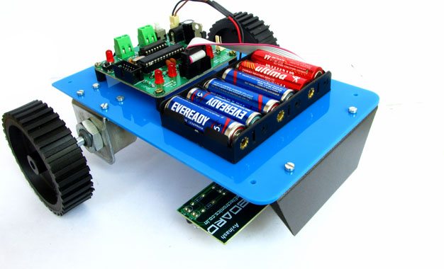
The Mechanical Construction of Robot.
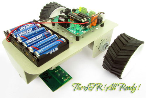 |
Final Assembled LFR |
The robot is build using common and low cost parts easily available online.
Mechanical Construct is described in detail here.
Electronics for the Robot.
The electronics for the robot is kept as simple as possible. The electronics board is split into to parts.
- The main board that has the MCU, basic MCU support circuit, motor driver and indicator LEDs.
- The line sensor board that is connected at the bottom part of the robot.
These two units are neatly connected using a FRC cable(see this).
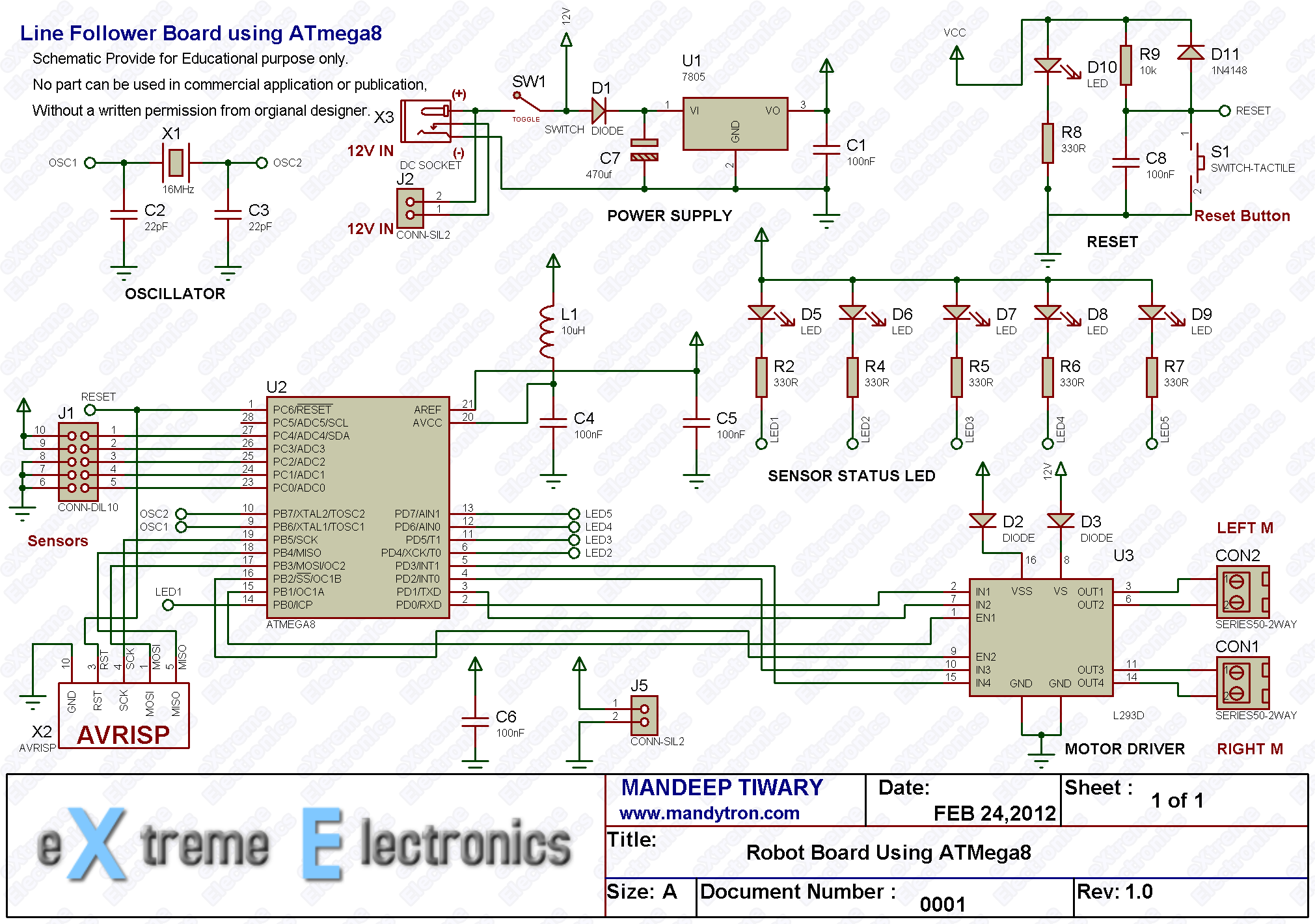 |
Main Board Schematic. |
The schematic for line sensor array is given in this article.
Purchase
You can purchase both the circuit boards made using high quality PCBs and parts. Simply follow the link. Our store accept online payment using debit cards, ATM cards and Net Banking. The products will be delivered to you door steps within 3-5 days any where in India using quality courier service.
- Fully assembled and tested main board.
- Fully assembled and tested line sensor board.
other wise you can build the circuits on a general purpose PCB or breadboard. But those are lot messy, bulky and does not fit well in the chassis. Beginners should avoid using them. You can save lots of time and pay more attention in the program part that is more important.
The program for LFR.
The LFR Program needs help from three libraries :-
- LED lib (to turn on/off five indicator LEDs)
- Motor lib (to control the speed and direction of rotation of motor)
- ADC lib (to configure and use the analog to digital converter of ATmega8)
The code is written using the C language so you need to be comfortable with the following.
- Syntax of C language.
- Concept of libraries.
- Source File, Header File etc.
- Preprocessor, Compiler and Linker, what they are and what they do and how to use them.
The IDE (Integrated Development Environment) that is a software suite that let you enter, edit, compile,debug project and manage files in project. The IDE that we are using is the latest Atmel Studio 6. Introduction to AS6 is here.
A new project is created as described in above tutorial and configured then the library files LED,Motor and ADC needed to be added to the project. Adding a library to current AS6 project is described in libraries manual.
/*
 * LFRM8.c
 *
 * Created: 5/26/2012 7:59:45 PM
 *  Author: Avinash Gupta
 */

#include <avr/io.h>
#include <util/delay.h>

#include "lib/adc/adc.h"
#include "lib/motor/motor.h"
#include "lib/led/led.h"

#define SENSOR_THRES 800

//Map Sensor Number to ADC Channel
#define SENSOR1 0
#define SENSOR2 1
#define SENSOR3 2
#define SENSOR4 3
#define SENSOR5 4

//Gloabal varriables
float pGain = 200;   //Proportional Gain
float iGain =  0.2;  //Integral Gain
float dGain =  120;  //Differential Gain
int delay = 10;

int32_t eInteg = 0;  //Integral accumulator
int32_t ePrev  =0;      //Previous Error


void  DelayMs(uint8_t ms);
float ReadSensors();
float PID(float cur_value,float req_value);


float control;
float s;

int main(void)
{
   //Initialize Motors subsystem.
   MotorInit();

   //Initialize LED subsystem
   LEDInit();

   //Initialize Analog to Digital Converter (ADC)
   InitADC();


    while(1)
    {
      //Previous Sensor Reading
      float sprev;

      //Take current sensor reading
      //return value is between 0 to 5
      //When the line is towards right of center then value tends to 5
      //When the line is towards left of center then value tends to 1
      //When line is in the exact center the the valeue is 3
        s=ReadSensors();

      //If line is not found beneath any sensor, use last sensor value.
      if(s==0xFF)
      {
         s=sprev;
      }

      //PID Algorithm generates a control variable from the current value
      //and the required value. Since the aim is to keep the line always
      //beneath the center sensor so the required value is 3 (second parameter)
      //The first argument is the current sensor reading.
      //The more the difference between the two greater is the control variable.
      //This control variable is used to produce turning in the robot.
      //When current value is close to required value is close to 0.
      control = PID(s,3.0);

      //Limit the control
      if(control > 510)
         control = 510;
      if(control < -510)
         control = -510;

      if(control > 0.0)//the left sensor sees the line so we must turn right
      {
         if(control>255)
            MotorA(MOTOR_CW,control-255);
         else
            MotorA(MOTOR_CCW,255-control);

         MotorB(MOTOR_CW,255);
      }
      if(control <= 0.0)//the right sensor sees the line so we must turn left
      {
         if(control<-255)
            MotorB(MOTOR_CCW,-(control+255));
         else
            MotorB(MOTOR_CW,255+control);

         MotorA(MOTOR_CCW,255);
      }

      //Delay
      DelayMs(delay);

      sprev=s;
    }
}

void DelayMs(uint8_t ms)
{
   uint8_t i;
   for(i=0;i<ms;i++)
   {
      _delay_ms(1);
   }
}

//Implements PID control
float PID(float cur_value,float req_value)
{
  float pid;
  float error;

  error = req_value - cur_value;
  pid = (pGain * error)  + (iGain * eInteg) + (dGain * (error - ePrev));

  eInteg += error;                  // integral is simply a summation over time
  ePrev = error;                    // save previous for derivative

  return pid;
}

float ReadSensors()
{
   uint16_t eright,right,middle,left,eleft;
   uint8_t     sensor1,sensor2, sensor3, sensor4,sensor5;

   float avgSensor = 0.0;

   eright=ReadADC(SENSOR5);
   if(eright>SENSOR_THRES)//Right black line sensor
   {
      sensor5 = 1;
      LEDOn(5);
   }
   else
   {
      sensor5 = 0;
      LEDOff(5);
   }

   // Read analog inputs
   right=ReadADC(SENSOR4);
   if(right>SENSOR_THRES)//Right black line sensor
   {
      sensor4 = 1;
      LEDOn(4);
   }
   else
   {
      sensor4 = 0;
      LEDOff(4);
   }

   middle=ReadADC(SENSOR3);
   if(middle>SENSOR_THRES)// Middle black line sensor
   {
      sensor3 = 1;
      LEDOn(3);
   }
   else
   {
      sensor3 = 0;
      LEDOff(3);
   }

   left=ReadADC(SENSOR2);
   if(left>SENSOR_THRES)// Left black line sensor
   {
      sensor2 = 1;
      LEDOn(2);
   }
   else
   {
      sensor2 = 0;
      LEDOff(2);
   }

   eleft=ReadADC(SENSOR1);
   if(eleft>SENSOR_THRES)// Left black line sensor
   {
      sensor1 = 1;
      LEDOn(1);
   }
   else
   {
      sensor1 = 0;
      LEDOff(1);
   }


   if(sensor1==0 && sensor2==0 && sensor3==0 && sensor4==0 && sensor5==0)
   {
      return 0xFF;
   }

   // Calculate weighted mean
   avgSensor = (float) sensor1*1 + sensor2*2 + sensor3*3 + sensor4*4 + sensor5*5 ;
   avgSensor = (float) avgSensor / (sensor1 + sensor2 + sensor3 + sensor4 + sensor5);

   return avgSensor;
}
The LFR Code Walkthrough.
The main program begins by Initializing three subsystems namely Motor, LED and ADC (for sensor input). The code is as follows.
 //Initialize Motors subsystem.
 MotorInit();

 //Initialize LED subsystem
 LEDInit();

 //Initialize Analog to Digital Converter (ADC)
 InitADC();
Then program enters into a infinite loop ( while(1) { //Main LFR Loop } ), this infinite loop keeps the robot follow line as long as it has power.
In the loop first thing we do is to read the sensor using the ReadSensors() we get a value between 1 to 5 as follows.
- When the line is towards right of center then value tends to 5
- When the line is towards left of center then value tends to 1
- When line is in the exact center the the value is 3
- Returns 0xFF if no line is detected.
- Return value may be fractional also, like it is 2.5 when line is beneath sensor 2 and sensor 3.
In case a line is NOT found we below any sensor we used value we got last time. This is done by storing the current line position in a variable sprev just before the end of main loop. This sprev is used as previous line position for the next loop.
Code:
s=ReadSensors();
 //If line is not found beneath any sensor, use last sensor value.
 if(s==0xFF)
 {
 	s=sprev;
 }
Now a PID algorithm is used to find out the control variable from the current position and required position.
Current Position it is the position of line as read by the sensors.
Required Position is 3 (to keep the line on the middle sensor whose number is 3)
Code:
control = PID(s,3.0);
Then we make the control variable come within a range of -510 to +510
Code:
 //Limit the control
 if(control > 510)
 control = 510;
 if(control < -510)
 control = -510;
When the control variable is more than 0 that means line is towards the left, so we need to take right turn to correct the error and bring the robot back to track. To do a right turn we need to make the right motor go slow by the amount of control (if control is less than 255).
Code:
MotorA(MOTOR_CCW,255-control);
if control is more than 255 then we need to make the right motor go in opposite direction by the amount of control.
This will create a much faster right turning.
MotorA(MOTOR_CW,control-255);
Similarly if control variable is less than 0 that means line is towards the right, so we need to take left turn to correct the error and bring the robot back to track. The whole code looks like this.
		if(control > 0.0)//the left sensor sees the line so we must turn right
		{
			if(control>255)
				MotorA(MOTOR_CW,control-255);
			else
				MotorA(MOTOR_CCW,255-control);

			MotorB(MOTOR_CW,255);
		}
		if(control <= 0.0)//the right sensor sees the line so we must turn left
		{
			if(control<-255)
				MotorB(MOTOR_CCW,-(control+255));
			else
				MotorB(MOTOR_CW,255+control);

			MotorA(MOTOR_CCW,255);
		}
For more information turning the robot please see differential drive mechanism.
Finally we delay a bit for next cycle and store the current line position (s) to variable sprev for used in next cycle.
 //Delay
 DelayMs(delay);

 sprev=s;
Programming the LFR Hex code to MCU.
Configuring the MCU
The MCUs fuse bits must be set as follows.
- LOW Fuse = 0xFF
- HIGH Fuse = 0xC9
 |
Fig.: Setting the Fuse bytes. |
Running the Robot.
Put batteries in your robot and place it in the flex sheet which has a line printed on it using black colour. Place the robot over the line. Switch on the robot and see the action.
Trouble Shooting.
If you are not lucky enough to get this working in the first try, don’t be much unhappy! First try to do every thing exactly as I told. Make sure you should not use any type of replacement parts like a 200 RPM motor because every thing need to be in harmony. Using a battery with higher voltage or high speed motor will make the robot go too fast to catch the line. Similarly using another surface than a flex will have different reflectance so the sensor will not be able to "see" the line.
If you are using exactly 100% same steps and parts and still not able to get the robot working. Leave a comment in a proper manner with sufficient details so that we can help you. And never use SMS language while leaving a comment. If you don’t have time to write then others also don’t have time to read!
Best of luck ! I am here to help all !
Downloads.
- LFR AS6 Project (load file LFRM8.atsln in AS6, the file is in the root of folder)
- LFR Hex File Ready to burn on an ATmega8
Check your understanding! Take a 1 minute test.
Written by
| |
| Line Following Robot Board |
| CLICK HERE TO ORDER |
| |
| Line Following Robot Kit |
| CLICK HERE TO ORDER |
| |
| Line Sensor Array |
| CLICK HERE TO ORDER |
| |
| USB AVR Programmer v2.1 |
| CLICK HERE TO ORDER |
| |
| 12v DC Gear Motor – 150 RPM |
| CLICK HERE TO ORDER |
| |
| High Quality Metal Chassis |
| CLICK HERE TO ORDER |
although project is good but mechanical construction is not working
@Sarthak
Thanks for pointing out the brocken link. It is now fixed !
Hello sir,
Will the bot follow the line if it encounters a junction. Suppose there is a point in the track from where there are 3 path sharp left, sharp right and straight path. How to handle such suitation. And how the bot behaves when we get a sharp 90 deg turn like sharp left turn in which sensor 1,2 and 3 are on line.
@Dibyaranjan,
Please do not be over smart. This is the basic line follower robot whose aim is to teach new comers in the field robotics and embedded systems. So its code is kept as simple and clean as possible.
I have not made it win international competition and so it does not has super complex and messy codes!
Please try to under stand the purpose of anything before cementing !
Sorry avinash….but i just want clear my doubt if PID controller can be used to detect a junction. Your works are always wonderful. Thanks
how can i chose a proper value of pgain igain & dgain
for pid control if i have faster motor or less no. of sensor
@Mohit,
Have a Zigbee link between the bot and PC, have a PC software for tuning PID parameters. Then run the bot and adjust the params till you get desired result, first dgain and igain are set to zero and gradually increases.
hello avinash! Grt wrk.. vry gud design. iv tried a simpler one bt dis s much better!
@Prajwal thanks !!!
Great, nice tutorial i must say, well elaborated, this is surely your best work 🙂
Hey ,
🙂 Great Job with this , brilliant tutorials all of them i’ve read till now.!!! 🙂
but one thing i wanted to know. where can we get these libraries that you mentioned in the project.
do you have a link to it?
or maybe if i can get a link to how to control DC motors with PWM?
alright i found the link . 😛
thanx a lot again!!!! 😀
can post t links to download that libraries …
can i get that link 🙂
Pingback: Advanced Line Tracking Code Using ATMEGA16 Micro-controller .
hi sir
i have created a simple line follower using 2 IR sensors and avr-atmega8 only. I want the bot to take a reverse turn when the black line ends and follow the same line again.Can you please help me out with the logic that i need to put in.
see first thing u need to have a end point like a T formation at the end of line then ur algo can do this ,or else setting a control to take a turn every times it looses line ,but this algo will be buggy if ur line goes far from the turning radius of the bot,and ultimately your bot will keep on rotating at a point so its better u have a T formation at the end at the line and get this detected by checking all the sensors are high , that is on line ,
it can be achive by two sensors also so you may not modify ur bot ,
problem in hex file size :
sir ,
i am writing the same code u have given in this tutorial
in AVR STUDIO 4 for atmega 8 , i successfully build this code but the size of hex file is 15-16 KB which is out of the memory range of atmega 8 which has 8KB memory
.
and the hex file generated by u in avrstudio 6 is of
7-8 KB size
.
please tell me what is the problem ???
@Mahendra
You don not fulfill the prerequisite no 4 mentioned above!
“Knowledge of Preprocessor, Compiler and Linker, what they are and what they do and how to use them.”
Everyone knows that in default setting any compiler’s optimization level is 0, and it is in debugging mode! Debugging mode code has a lots of extra code in it in addition to the actual application code.
I don’t know from which damn place you have learnt C programming that you don’t know this ! Great pity !
People don’t try to understand thing that they are using! they always hit the wall and say hey this is NOT working and I am clueless why ! That is because you don’t know your trade right ! Or may be you are not made for it ! Go Try Something else.
BTW after a long philosophy class here is the quick solution that you are every fool is looking is here !
Go to Project Menu->Configuration Options Set Optimization to O2. By default its O0.
it’s still not working ,
the hex file size is same again
.
Do I have to tell you have to Click “Rebuild All” and NOT “Build” after changing optimization setting?
sorry but still file size is 15KB
.
i have also write a lots of program for line follower , wall follower ,program related to accelerometer for gesture control robot
but the hex file size did not exceed more than 2-4 KB
try making optimisation os taht may may help,i dont know realy but last time it worked for me
and may be compiler is adding up some extra code so better try the compilation off the avr studio i mean using winavr
use the mfile in win avr to create a new make file and for win avr you need to have the make file in the same directory as main.c else it will not complie ,
Avinash Sir can I use Atmega 16 in place of Atmega 8.This will reduce my cost as I donot have Atmega 8.Otherwise I will have to purchase atmega 8.Reply sir.
Since my connection is made as per ATmega8 and the program is also designed and compiled for ATmega8 it is easiest to use ATmega8.
If you want to go for ATmega16 you have to change the connection and also the program.
Which will unnecessarily increase the troubles!
Q1.Sir please tell why capacitor c6 is shown isolated in the LFR circuit diagram do I have to connect this c6 same as shown ie in vcc and ground anywhere in my zero pcb?
Q2.What is J5 in the diagram,I am a beginner please guide me?
Q3.And the AVR pin diagram shown in the circuit diagram has pin no.2 NOT CONNECTED OR it is vcc.Also is this ISP pin diagram is for 10 pin(as of the programmer in your website store)or 6 pin?
Sir please guide me,I have put my tremendous hard-work and lot of money to make this LFR.My zero pcb is 90%complete.I am a begginer
I trusted your site so started this project.Please guide me for above problems.I know you will surely help me.
@Inertia,
You are an engineer? Well you don’t know the grammar or may be the alphabets of an electronic schematic ! 🙁
That’s why you couldn’t read it !
Its called a by pass capacitor, and why the hell you are telling it isolated ?
Its connected to the power supply and ground.
Its placed close to the MCU’s power pins.
Jumper j5 provides 5 volt output.
THANKS SIR,
Your scoldings are genuine and I will work hard to be a genuine engineer.
SIR,please answer where to connect pin no.2 of avr isp male connector of LFR circuit(either NOT CONNECT or vcc?)?
I am confused with this pin no.2!Also sir rest of the pins should be left to “NOT CONNECTED”??(i.e,pin no.6,7,8,9)?
sir i saw ur project its very nice. I am a beginner and so i wanted to make line follower robot and i got every detailed information about it here. Thanks for explaining it so nicely. soon am going to start making a line follower robot as i have to show it in open day of my college.
All those pins of AVRISP are NOT Connected.
thankyou sir!
Sir reply soon
Hay ,
Can I have the proper method of making sensor circuit and motor board please ??
sir ……how to make a program for sensor circuit which feeds analog values to mcu …..for a line follower …
sir,
can this coding ,which you have given, work for ATMEGA16?
And i have already converted analog signal to digital using comparator…….what changes should i make in that code??
@Ayush,
No this code does NOT work for ATmega16 for without modification. And I have NO free time to personally help anybody! Ok!
Only silly designer use external comparator.
sir, i wanna know how can we increase the speed of the bot
also provide me some informatin on PID control (the confused part for me in the pid code is calculating the weighted mean) i heard rather read people saying that the calculation of the weighted mean belongs to the inverse kinematic part ,if possible explain this part ,rest of the part i seem to understand ,
The above given code works only for a 150 rpm motor….But the problem is that our competitors are using a 300 rpm motor…So we wanted to know that if you are having the same kit everything same but supporting a 500 rpm motor…If its available with you please contact asap….
sir, the circuit diagram of this project is so small..i zoom this….bt the apparatus is not clear to understand….sir, if u give me the chart of the apparatus of this project..its very convenient for me
Hello sir,
I want to know how to turn this program to a grid solver program.
Can you please make the program?
It would be very grateful of you
Thanks
Pingback: Build and Program a Line Following Robot Using AVR ATmega8 | Building Robotics News
awesome article man….
respect
sir,
could u pls tell me about the implementation of robotic car using motion sensors..i want the circuit of it.
hi
mr avinash, its good to see ur site. pretty good and a good learning experience, but u seem to be too rude in replying to the questions, pardon their ignorance. Not every one is as bright as u r, not every one would have had a formal electronics background, got to be a bit more polite to encourage people reading or leaarning from u r site
bye
Can u help me tweaking it to detect perpendicular cuts in the track and to follow a white line on a black background rather than black line on a white background??
please send me the link to access library files..i need it soon..
Buy the KIT to get libs.
i need the library files too… someone plz help
Buy the KIT to get libraries.
hello sir i am just a 11 year kid and i am interested to become a robotic scientist i formed an e-mail id with my parents only for learning robotics .PLEASE help me to learn from very beginning and also tell me the software that i can use
Hello ! I have searched many articles to study PID code. I want to ask why do you not include the TIME factor when taking integral and derivative ? Tell the reason for it. I want to combine Fuzzy Logic + PID to make a feedback control system for a simple incubator.
I followed your tutorial and bot is working fine. It is working great on smooth turn even at full 150 rpm but facing difficulty in sharp 90 degree turn.I tried to calibrate PID value. Now its working fine for right turn but facing difficulty in left turn.I would be very thankful to you if you can help.
Pingback: List of Embedded Projects with project report | Just Share Here
this is one of the most completed tutorial to build a simple line follower robot. thanks!
Dear Sir,
You are right that line senosr schematic is very clear. I meant main board schematic (although outer details are good and inner details are not clearly legible). with thanks Dr.C.Karunakaran
@Karunakaran,
I am also talking about the main board schematic only !
@Avinash Post author
Bro can you came on mail box.., plz need to knw a lot bout my projects..,
superb its really awesome (Y)
i also i made in technical fest in pec chandigarh and i got 3 piostion but how can we manage speed avinash sir???
sorry but it is very difficult to understand by 7th standard boy like me
“line is towards the left, so we need to take right turn ”
Could’nt understand this logic where you have to turn right when the line is directed towards left????
@Arun,
Sorry it is a mistake. It should be “line is towards the left, so we need to take LEFT turn ”
please explain about control =510,control=-510, i mean how that 510 came should we calculate anything
Dear sir,
i always follows your post and tutorials and like very much.
i’ve some question that, in this line follower tutorial you use your development board and create custom library files. but i don’t have any commercial AVR board. Can it be use the library without using the XBOARD? if it
possible then what should i do? i want to build a LFR for my final year project.
please reply at samim.me.bd@gmail.com
Thanks 🙂
avinash sir,
please help me… as soon as possible…. i have made a line follower robot using two sensors… and line follower robo using single sensor too…. but i have got pissed… in making it a grid solving bot…. i’ve only two sensor sockets in my mother board but i dont think grid solver can be made using two sensors only….. we can make it using single sensor by wall following algorithm but… it dont know how to make it differentiate a T-point and home…….. i am first in first year engineering, mechanical branch, but i know a bit C++……. so i dont know about delay func that much but i know it would help me in differenciating the T point and home…. kindly help me out… should i use any other ic or mother board or… should i replace my leds with some new sensors???
Hi.
I’m buying this kit. I would like to know whether the ATMEGA8 used is same as atmega8l-8pu ?
like, if i replace ATMEGA8 that comes with the kit and use atmega8l-8pu instead , would the code execute successfully ?
@Afsal,
Consult documentation available at Atmels website.
Hey avinash.. Great project.. By the way can you help me out with the library motor.h.. From where can I get it.. If you could kindly help.. 😀
@Bikash see the DVD you should have received with the kit.
we hav tried to design line follower with six sensors but the output is not coming …can u help us wid the coding ???? pls do reply
sir the value of control which you hav taken from +510 to -510 ..does this value change with the number of sensors … if the number of sensors is 6 what value of controls should we take …. pls reply as soon as possible
Hi sir,
Its not working for me. I am using 200rpm motor. Is that causing a problem? Can you please tell me how to access the library files?
If you are unable to make from the information provided. Please get a fully tested kit from here.
http://store.extremeelectronics.co.in/LFR-Kit.html
My LFR is not following the line drawn…please help me out how can I check that my Infrared sensors are working properly please do let me know…
@Ankur,
Did you purchased the KIT from our store?
This article is actually a nice one it assists new internet viewers, who are wishing for blogging.
Dear sir,
I am looking for your address. Please provide me the same
sir., there is any chance to extend this line follower to MOBILE CONTROL ROBOT
Pingback: What are the best sites or blogs that may be useful in designing an advanced line follower? - Quora
sir
i want to know about the functions of all the components in atmega 8 development board
sir!
first of all thank u for guiding us indirectly in such a proper way…sir! i would like to ask u dat is dere any option to test individually sensor board rather than to go for the next step to design the main board…i m jsz asking becoz rather than going to the nxt step,i want to be sure whether the sensor board i designed is properly working or not???..plz reply asap.
thank u
rajesh
@Rajesh Rajan,
You can provide 5v to the sensor and then check its output using a digital multimeter. If you bring some white surface in front of the sensor, the voltage output should change.
thank u sir for giving such a quick and proper response.hope it will work fine nd in case i face any problem,then i will contact u further!
thank u!
Rajesh
HI, i am a newbie here, and is making a new robo, a LFR, but cant make it turn. i am using a Spark Lab PCB, ATMEL Atmega8 MCU, L293D Motor Driver, two motors and two IR Sensors with two plastic tyres and a plastic chasis, you can find it on sparklab.in,
so, the problem is that when i want it to move some distance and give some delay, it doesnt give a delay but moves forward contoniusly, and when i gave sensors command, it senses the black line but dont turn towards it, you can get the datasheet of the board on sparklab.in
Can anyone please give me the code to make the LFR correctly??
i’ll be greatful to you.
my emails is ishaanprasad.ip@gmail.com
Can you plz tell me the values of Diodes D1 , D2 , D3 ?
i have got other components but can’t figure out those . . .
plz reply as quickly as possible as this is going to be my project for this year’s TECHFEST in our College . . .
Waiting for reply . . .
@Jalaj,
Why don’t you purchase the KIT from our store?
where can i get those lib files ?
coz i want to learn how to build so i am not buying it
@Jalaj,
If we send those lib files to you would you be able to make it yourself? Or if you come to us for anyother problems that may arise in your path?
And write comment in proper english only ! otherwise they would be deleted!
My apologies for not using proper english.
I will try my best to complete the project. And if any problems i will try my best to solve it on my own.
Also i hope that you may help me in my worst case problems and assist me.
@Jalaj,
Please share this page on your Facebook profile. And like eXtremeElectronics on Facebook. Then we will mail you the library files.
sir can u plz say me how to write a program for lcd display&7-segment in line follower bot using ATmega8 aurdino micro controller
this site is great to learn something..
thanks avinash sir..
@pramod shah, welcome.
Sir, would you please provide me the library files. I want to make this robo for my collage competition and please tell me may I use 2 wheels for front instead of a 360° rotating wheel?
Sir I have made line follower it’s working BT when path overlap each other both the sensor come on black surface nd stop working can u help out plzz it’s my mail I’d rupaliadsule0750@gmail.com
I just want to know a programming of A single IR module(as input of MCU) interfacing with Atmega8 for giving a simple output LEd glow….??
sir you are doing a great job, will you please send me the library files ? i will be very thankful to you for this act
Hi sir
How to send data from vb to microcontroller at89s52
Sir, can i have the code for adc?
Sir,
I changed the fusebits like in the tutorial and now I can’t connect with uM. What should I do?
You need to properly connect the crystal oscillator during programming also, then only it will respond.
sir when i wast write fuse bit the programmer was enable to detect atmega 8
ii am using usb asp v2.0 icsp programmer
before writing the fuse bit it was detect properely
Because you have NOT connected a crystal to ATmega8. Now without a crytal it wont run. And also not get programmed.
Pingback: Robot C Error 42
Dear Mr. Avinash,
I happened to see this tutorial. Thank you for he elaborate instructions. As a beginner into robotics, I should thank you for encouraging people like us….God bless!
Regards,
Lakshmikanth