Stepper motors pairs nicely with a smart device like a microcontroller to create precise digitally controlled movements that has made possible many of modern gizmos around us. For example a printer, scanner, plotters, fax, floppy drive (not so modern though!), automatic industrial machines like CNC (Computer numerically controlled) drills, laser shows etc. Though to a naked eye the motor of stepper look no other than a DC motor but the difference is that each step of a stepper motor is in control. For example a high speed desktop printer when the paper moves forward, to a novice it seems like a motor is just pushing the paper out but in reality the control board inside the printer request the motor to move the paper exactly same amount that has been printed. This precise movement keeps the next printed pixel in alignment with previously printed pixels.
The thing is that the stepper motors have certain amount of steps per full 360 degree rotation (exact number depends on model) the controller can request the stepper to rotate any number of steps. For example if you are making a robot, you want it to move exactly as per your program. Like if you say go forward 100cm then rotate right 45 degrees and move forward 50 cm. You cannot do this with DC Motors, because for it you need to calculate the exact speed for DC motor and then use blind timing for movement. Say if you happen to find out the your robot moves at 5cm per second then to move 100cm it will require 20 second. So you keep the motor on for 20 second and expect that it has moved 100cm. But this can prove failure if the speed of robot changes due to drop in level of battery or some additional weight or simply due to an uneven terrain etc. So this method is not so trustworthy.
The second method is the use of stepper motors. Say you have a stepper motor of 7.5 degree per step (that means it move 7.5 degree for single step or their are 48 step in full rotation) and their is a gear reduction of ratio of 1:75 then you can control the stepper with an accuracy of 0.1 degree per steps! wow! that’s really precise! Now if we assume you have attached a wheel of radius 3.5 cm then you can control the liner motor of your robot with an accuracy of 0.00611 cm (I leave the math on you). That’s pretty decent. To move the motor forward 100cm, you just need to step the motor 100/0.00611 times that is 16,366 times. Instead if you step it 16,202 times it will move 99cm. So now the bot is pretty much in your control.
In the same way PCBs are drilled at accurate position, SMT components placed automatically at their desired location, pixel on a paper are printed. Below are some videos that may help you get the point.
Types of stepper motor
Their are many types of stepper motors available but the two most common types are
- Unipolar Stepper Motor– Has simple driver requirement. Less torque at same size and weight as compared to bipolar type.
- Bipolar Stepper Motor – Has slightly complicated driver requirement. More torque at same size and weight as compared to unipolar type.
Since the Unipolar type is simpler to drive we will start our journey with it.
Driving Stepper Motor with AVR MCU
In the figure below is shown a simplified construction of a stepper motor. The center is a permanent magnet(PM) rotor. Around it are four electromagnets. One end of all four electromagnet is connected to a point called "common". The common is usually connected to the stepper supply voltage (eg. 12v). The four coils are named A,B,C and D. To rotate a stepper motor, coils are excited in turns like A,B,C,D. The rotor will try to align itself with the currently exited coil. Lets say that the white point shown on rotor is magnetic north pole. Also assume that when coils are excited, their inner end becomes magnetic south. So the white point on rotor will try to align with the currently excited coil.(As the opposite poles attract)
 |
Simplified Construction of Stepper Motor |
So to drive a stepper motor from AVR MCU you just need to excite the coils A,B,C,D in turns to rotate the motor in anti clock wire direction. If you want to rotate the motor in clock wise direction simply excite the coil in reverse order that is D,C,B,A.
As the port of AVR can only sink or source 20mA current approximately, they cannot be used to drive the the coils directly. So we need some thing that can boost this current. The part that fit perfectly in this scenario is ULN2003A. It is a high voltage, high current Darlington array. It can be driven directly with a TTL level input and the output can source up to 500ma. Since it is array of seven darlington pair, (of which we require only four) it is much compact.
 |
ULN2003A Powering a Stepper |
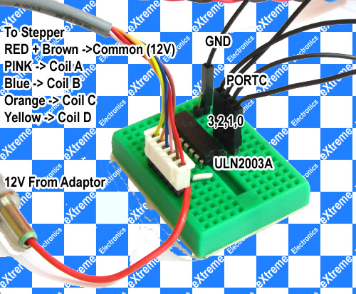
In this example we will use PORTC to drive the stepper motor. So we connect PIN 1,2,3,4 of ULN with PORTC 0,1,2,3 of PORTC. The output is available on pin 16,15,14 and 13 of ULN IC. These are connected to the four coils A,B,C and D of stepper motor. The common of stepper motor is connected to 12v supply from the adaptor. The pin 8 of ULN2003 IC is connected to GND (common of system). The whole connection can be made on a small bread board like this.
 |
ULN2003A Powering a Stepper |
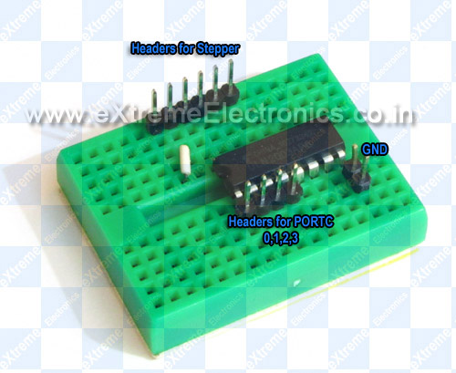 |
ULN2003A on Breadboard |
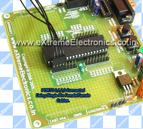 |
PORTC on Dev Board |
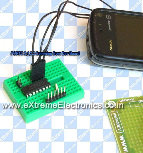 |
PORTC Connected to ULN2003A |
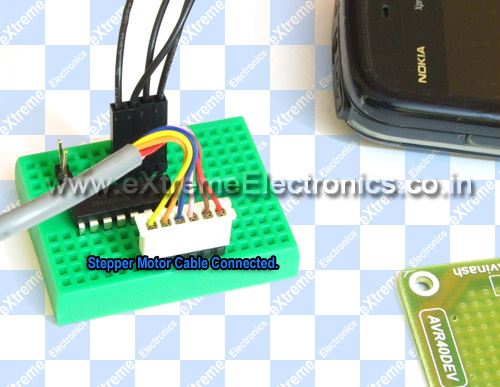 |
Stepper Also connected. |
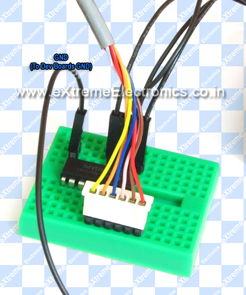 |
Ground PIN of ULN2003A |
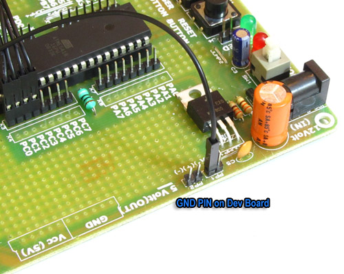 |
GND Pin on Development Board |
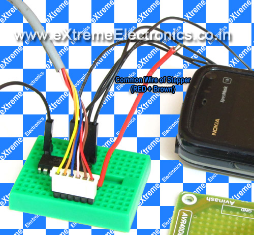 |
Common Wires of stepper |
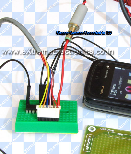 |
Common wires of stepper connected to 12v |
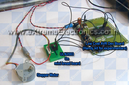 |
The whole setup!Stepper, ULN2003A, AVR ATmega16 on Devboard |
avr-gcc source code for stepper motor
Here I will present a small and simple library to drive a single stepper motor. The library supports port configuration that means you can change in which PORT stepper is connected. Their are only three function in the library.
- void StepperInit()
- Must be called before calling any other stepper related function. This function configures the related PORT pins as output.
- void StepperStepCCW()
- Steps the stepper in counter clock wise direction.
- void StepperStepCW()
- Steps the stepper in clock wise direction.
The library is provide in two files. These two files must be copied to current project folder and added to the AVR Studio Project.
I am also providing a sample which demonstrate the use of above functions.
/******************************************************************************

Title:

   Demo program to show the use of simple stepper library.

Description:
   A unipolar stepper motor connected to PORTC0,1,2,3 via
   driver IC ULN2003A.

   The stepper should be a 15 degree per step with approx
   1:85 gear reduction.

   The ATmega16 MCU Must be clocked by a 16MHz crystal

   Fuse bits must be set as follow to disable JTAG and use
   external crystal.

   LOW FUSE    = 0xFF
   HIGH FUSE   = 0xC9

   For More information visit
   http://www.eXtremeElectronics.co.in
   (then search 'stepper motor')


Author:
   Avinash Gupta.

   avinash@eXtremeElectronics.co.in

Copyright:
   eXtreme Electronics, India 2008- 2011

Notice:
   No part of this work can be copied or published in electronic or
   printed form without proper permission from the Original Creators.

   ONLY INTENDED FOR EDUCATIONAL, HOBBY AND PERSONAL USE.
   COMMERCIAL USE IS STRICTLY PROHIBITED.


Disclaimer of Warranty.

   THERE IS NO WARRANTY FOR THE PROGRAM, TO THE EXTENT PERMITTED BY APPLICABLE LAW.
   EXCEPT WHEN OTHERWISE STATED IN WRITING THE COPYRIGHT HOLDERS AND/OR OTHER

   PARTIES PROVIDE THE PROGRAM “AS IS” WITHOUT WARRANTY OF ANY KIND, EITHER
   EXPRESSED OR IMPLIED, INCLUDING, BUT NOT LIMITED TO, THE IMPLIED WARRANTIES
   OF MERCHANTABILITY AND FITNESS FOR A PARTICULAR PURPOSE.
   THE ENTIRE RISK AS TO THE QUALITY AND PERFORMANCE OF THE PROGRAM IS WITH YOU.
   SHOULD THE PROGRAM PROVE DEFECTIVE, YOU ASSUME THE COST OF ALL NECESSARY

   SERVICING, REPAIR OR CORRECTION.

******************************************************************************/

#include <avr/io.h>
#include <util/delay.h>

#include "xstepper.h"

void main()
{

   //Initialize the stepper library
   StepperInit();

   _delay_loop_2(10000);

   while(1)
   {

      for(uint16_t i=0;i<24*85;i++)
      {
         StepperStepCW();     //Step Clock wise

         _delay_loop_2(10000);
      }

      for(uint16_t i=0;i<24*85;i++)
      {
         StepperStepCCW();    //Step Counter Clock wise

         _delay_loop_2(10000);
      }
   }

}
The sample code first runs the stepper full 360 degree in clock wise direction and then full 360 degree in counter clock wise direction. This process is repeated as long as the board is powered. The code can be compiled using WinAVR Compiler using the AVR Studio as front end. For more details on installing and using this tool please see the following tutorial.
Compile the above program using AVR Studio (compiler is avr-gcc). And finally burn the program using any ISP Programmer to the ATmega16. The fuse bits must be set as following to enable external crystal as clock source.
- High Fuse = C9 (hex value)
- Low fuse =FF (hex value)
After burning the HEX file to MCU, finally you are ready to power up the setup.
Videos for stepper motor control using AVR
Downloads
- HEX File for ATmega16/ATmega32 running at 16MHz
- Complete AVR Studio Project (load the StepperTest.aps in AVR Studio)
Things Required
- A Unipolar geared stepper motor.
- ULN2003A IC
- Breadboard (Can be used for other projects too!)
- Male Headers 15mm
- Single pin female to female wire
- 40 PIN Low Cost AVR Development Board. (Can be used for other projects too!)
- USB AVR Programmer.(Can be used for other projects too!)
Help Us!
We try to publish beginner friendly tutorials for latest subjects in embedded system as fast as we can. If you like these tutorials and they have helped you solve problems, please help us in return. You can donate any amount as you like securely using a Credit or Debit Card or Paypal.
We would be very thankful for your kind help.
Subscribe!
Don’t miss any article get them right in your inbox! Subscribe to our feeds powered by Feedburner.
By
Avinash Gupta
www.AvinashGupta.com
me@avinashgupta.com
More and more Productive these days you are with lots of pics and vids..!
But i din get one thing ..do the gear assembly to stepper is by default or need to arrange our custom gear assembly?
@feelpavan
Thanks.
Photography is my new hobby now.
The stepper I have shown comes with a built in gear mechanism. Other steppers without gear box is also available.
-Av
Pingback: Electronics-Lab.com Blog » Blog Archive » Stepper motor tutorial
Man u r goooooD!!!
First Thank you for publishing one more great tutorial. I have one question, may be very silly to you, Here you are showing how to get position by stepper motor , but what about speed, how to control the speed or how to achieve the desired speed to get desired position. please reply.
regards,
Uttam
One more thing – although Pics will be very helpful but straightforward schematic is expected, please provide schematic as provided in earlier tutorial,
Regards,
Uttam
@Uttam Dutta,
The speed can be controlled very easily just by changing the delay between steps.
In the above snippet, just change the delay between steps by changing the value of parameter passed to _delay_loop_2()
But note one thing if the delay is too small (very fast rotational speed) the stepper simply wont start. It will sit their making humming noise.
To achieve faster speed you need to ramp up the speed. That means start slowly and increase speed gradually.
But to mimic the function of a DC motor with a stepper isn't a good idea. Its not what stepper meant to be.
To Mr. Avinash,
Thank You so much for reply and expalntion, I am excitaed to build it as soon as I get the stepper motor.
can you please provide detail schematic of hardware , this helps to experiment without readymade kit .
Regards,
Uttam Dutta
Can we use atmega8 for stepper motor control
what is _delay_loop_2() actually? where I can find the details of this librery function? does it take arguments in ms? what is the meaning of passing argument 0?
I have searched in AVR studio 5 regarding this but I cant find anything
waiting for earliest reply….
Hi there, thanks for all the tutorials you have publish. I see that your stepper has 6 wires, what’s the difference between one of 4 wires ? How can this be controlled ? Thanks in advance.
P.S. Keep on going with this site, it’s magnificant !
@Vlad,
That one is a bipolar stepper motor.
Thanks for your tutorial.
How to rotate the stepper motor 180 degree or 90 degree?
Pingback: problem with Servo and Stepper motor
Can i use Atmega8-pu or it have to be atmega16a-pu?
Can i use ULN2003APG instead of ULN2003A?
why 24*85 in for loop??
Sir
If I want to use stepper motor with 1.8 deg step angle where do i have to change?
I mean to say i change 24*85 with 200 but its not working. its causing only huming noise.
Hey Avinash , this is harsha. I bought a unipolar 12v stepper motor from your website, it didnt have any connector with it, so I’m facing difficulty as to identify the which pin is for which Coil and which pins are the common … can you help me asap ….
Thanks for your tutorial!
How can I get this software?
WE CANT JUST RUNS TWO STEPPER MOTORS WITH ONE IC.THIS IS THE LAS RESUALT I CAN FIND AN GIVE THEM TO YOU PLZ BE PATIENT AND WAIT FOR MORE RESAULT.IM WAITING FOR YOUR COMMENT PLZ IF YOU FIND A WAY TO RUN TWO STEPPER MOTORS KEPP US KONWING.TNX
I dont know what I would have done without this tutuorial , thank you so much ! It is so lucid and comprehensive that even a slowpoke like me can understand and grasp very clearly . Do keep posting more of this brilliant stuff !
thank you Avinash for such a easy and understandable article about Stepper motor controlling with AVR. heart full saying really nice! keep it up.
Thanks for this tutorial. But if I want to change the direction of the rotation using keyboard controls, how would that be done?
And also what kind of Uni-polar motor (specification) should I buy that would be appropriate for the IC ULN2003A.
I will be thankful if you help.
Hi Ashwini, we will glad to help you. But can you tell me , What kind of keyboard you want to use ?
is it ok to connect micro-controller directly wit driver???
dont v need an opto isolator?
I would also connect pin 9 of the ULN2003A to the Stepper Motor’s common 12V. This will shunt any EMF safely.
hey ….
seriously dis tutorial is awsome . right now iam working on a project (like robotic arm), using servo motors, i just wanted to know if the operating part of servo motors could be done by some gear system , i mean the mechanism… or is it that we have to go for computer based programming only .
Dear sir,
In this tutorial, what is the resolution of the motor we are getting?Is it 90 degrees per step and what about half stepping to double the resolution?
Hi Avinash, Hey i have slightly noticed that your library header (Include) isn’t similar to the one you have in your “.c” you have XSTEEPER_H in your “.h” yet you called “xstepper.h” in your main was it meant to be like that?
Cheers.
hello sir i want your phone no.
sir while executing this code in AVR STUDIO 4,,am getting an error that #include “xstepper.h” directory does not exist..how to debug it sir?
@abhishek,
now it has been updated to be compiled with Atmel Studio 6.
If you need our help then you first need to share this page on your Facebook profile.
Hi Avinash, i am working on a project similar to this, its the incandescent lamp dimming. i want to control the dimming using a 4×3 keypad for 20% 40%….100%. how would i go about coding the keypad so that it dims the lamp accordingly? i am using atmega16, your help would be highly valued.
hiii i want assembly prog for atmega8535 to rotate stepper motor 180 degree…after432sec it should give one pulse
Hello Everyone,
I am working on stepper motor control using arduino pro mini board and A4988 stepper driver .I am connecting external power supply of 12V to run the motor.I have connected 3 and 5 pin on mini for step and direction of stepper driver.I have connected 4 wires of motor seeing datasheet for motor model Nema 17.I am not able to run my motor by following arduino code.Assistance would be appreciated.
const int stepPin = 3;
const int dirPin = 5;
void setup() {
// Sets the two pins as Outputs
pinMode(stepPin,OUTPUT);
pinMode(dirPin,OUTPUT);
}
void loop() {
digitalWrite(dirPin,HIGH); // Enables the motor to move in a particular direction
// Makes 200 pulses for making one full cycle rotation
for(int x = 0; x < 200; x++) {
digitalWrite(stepPin,HIGH);
delayMicroseconds(50);
digitalWrite(stepPin,LOW);
delayMicroseconds(50);
}
delay(1000); // One second delay
digitalWrite(dirPin,LOW); //Changes the rotations direction
// Makes 400 pulses for making two full cycle rotation
for(int x = 0; x < 200; x++) {
digitalWrite(stepPin,HIGH);
delayMicroseconds(500);
digitalWrite(stepPin,LOW);
delayMicroseconds(500);
}
delay(1000);
}