When you start working with LCD modules you will start feeling the real power of MCU and your imaginations will be touching sky you will wonder how many exciting a powerful gadgets you can create and that’s so very easily.
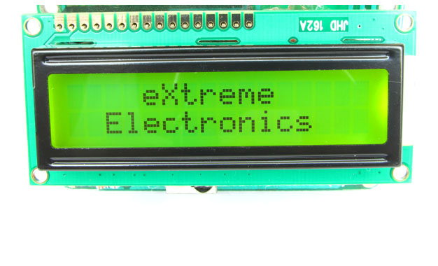
LCD Modules can present textual information to user. It’s like a cheap “monitor” that you can hook in all of your gadgets. They come in various types. The most popular one can display 2 lines of 16 characters. These can be easily interfaced to MCU’s, thanks to the API( Functions used to easily access the modules) we provide. LCD interfacing is just fun !
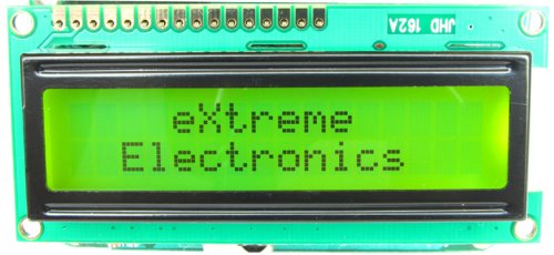 |
Fig: A 16×2 LCD Module |
PIN Configurations.
The lcd modules has 16 PINs for interfacing. The details are given below.
| LCD Module Pin Configuration |
| 1 VSS (GND Supply) |
| 2 VCC (+5V) |
| 3 VEE (Contrast Adjust) |
4 RS |
5 R/W |
6 E |
7 DB0 |
8 DB1 |
9 DB2 |
10 DB3 |
11 DB4 |
12 DB5 |
13 DB6 |
14 DB7 |
15 LED + |
16 LED – |
Connection with ATmega8/ATmega168 etc.
The lcd module can be easily connected to the any 28 pin AVR MCU like ATmega8/ATmega168/ATmega328 etc. The diagram below shows the LCD connection with AVR MCUs port pins.
 |
Fig: Connection with 28 PIN AVR MCUs |
Connect the required pins of PORTB and PORTD as shown in the diagram. The PORTs are clearly marked in the board. For connection you will need single pin female to female wires. Supply the LCD using the onboard 5V supply output using a 2 PIN connecter. Leave D0-D4 of LCD unconnected.
Connection with 40 PIN MCUs like ATmega16/ATmega32
 |
Fig: Connection with 40 PIN AVR MCUs |
NOTE: The 10K Pot (RV1) is very important, so please don’t omit that ! When powered on for the first time you need to adjust this pot to get a clear display. Without proper adjustment of this pot you can even get a completely blank display !
Prototyping Become much easier and looks neat if you use a Low Cost Development Board and a LCD Board.
The low cost development board has all the basic circuitry to support AVR MCU, while the LCD Board has all the basic circuitry for supporting LCD Module. Both the boards can be connected using a single pin female to female wires.
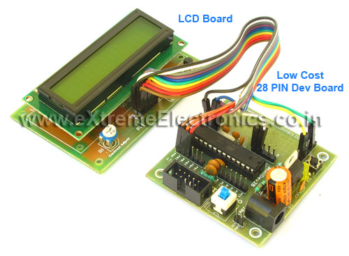 |
Fig. Interface with ATmega8. |
Adding LCD support to your project
To add LCD support to your C projects we have made a easy to use library. To use this library first create a new project in AVR Studio then copy the following files to your project folder. lcd.c lcd.h myutils.h from lcdlibv20.zip then add them to your project by right clicking project view and selecting “Add Existing Source File(s)…” and then select the “lcd.c”. Similarly add “lcd.h” and “myutils.h” in Header Files section. Now you are ready to start coding LCD applications !!!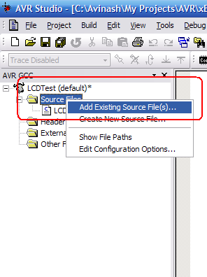 |
Fig: Adding files to projects. |
Programming.
In your main C file include the file lcd.h as #include “lcd.h” then initialize the LCD subsystem using a call to LCDInit(LS_BLINK|LS_ULINE); the argument specify the type of cursor required the LS_BLINK gives a blinking cursor. LS_ULINE gives a underlined cursor. To write any text call LCDWriteString(“Welcome”); To write any number call void LCDWriteInt(int val,unsigned int field_length); This will print a integer contained in “val” . The field length is the length of field in which the number is printed.
For example LCDWriteInt(3,4); will print as follows
 |
While LCDWriteInt(123,5) will print as follows.
 |
To goto any particular position on screen call.
| void LCDGotoXY(uint8_t x,uint8_t y); |
| LCDGotoXY(11,1); |
 |
Fig: Cursor Positioning. |
Now anything you write to LCD will be printed at (11,1).
Clearing the display
| LCDClear(); |
This will clear the display and bring the cursor back to (0,0). There are two more functions that will go to specific position and print in one call.
Writing Text at a specific position.
LCDWriteStringXY(x,y,msg);
____________________________
x,y : the location where to print “msg” msg : the message to print Ex: LCDWriteStringXY(3,0,”hello”); LCDWriteStringXY(8,1,”world”); Output:
|
Writing Number at a specific position.
Similarly there is a function for integers.
LCDWriteIntXY(x,y,num,field_length); ____________________________________ x,y : the location where to print “num” num : the integer number to print field_length : the length of field (see LCDWriteInt() function above). |
Sample Program
#include <avr/io.h>
#include <util/delay.h>

#include "lcd.h"

void main()
{
   unsigned char i;

   //Initialize LCD module
   LCDInit(LS_BLINK|LS_ULINE);

   //Clear the screen
   LCDClear();

   //Simple string printing
   LCDWriteString("Congrats ");

   //A string on line 2
   LCDWriteStringXY(0,1,"Loading ");

   //Print some numbers
   for (i=0;i<99;i+=1)
   {
      LCDWriteIntXY(9,1,i,3);
      LCDWriteStringXY(12,1,"%");
      _delay_loop_2(0);
      _delay_loop_2(0);
      _delay_loop_2(0);
      _delay_loop_2(0);

   }

   //Clear the screen
   LCDClear();

   //Some more text

   LCDWriteString("Hello world");
   LCDWriteStringXY(0,1,"By YourName Here");    // <--- Write ur NAME HERE !!!!!!!!!!!

   //Wait
   for(i=0;i<100;i++) _delay_loop_2(0);

   //Some More ......
   LCDClear();
   LCDWriteString("    eXtreme");
   LCDWriteStringXY(0,1,"  Electronics");

}
Advance Use – Configuring Connections.
The library is designed to be fully customizable. If you want to connect the LCD module to some different i/o ports of the MCU then you can do so easily. You just have to modify the lcd.h file. Let’s see how. Open lcd.h and find a section “LCD Connections” it looks like |
Fig: Configuring LCD Connection. |
Set LCD_DATA to the port where you have connected the LCD data lines. Then set LCD_DATA_POS to the starting pin of data lines. The LCD data lines D4 to D7 must be connected to consecutive pins starting from LCD_DATA_POS. For example if you wise to connect like this.
| PORTD (MCU) | 0 | 1 | 2 | 3 | 4 | 5 | 6 | 7 |
| DATA LINEs (LCD) | D4 | D5 | D6 | D7 |
You must configure like this
#define LCD_DATA D //Because we are using PORTD
#define LCD_DATA_POS 3 // Because LCD DATA4 is connected to PD3
Please note that LCD Data lines DATA0 to DATA3 are always unused only DATA4 to DATA7 are required.
The library uses advance 4-bit mode so DATA0-DATA-3 of LCD are not used, saving 4 MCU pins! Now set the port where you have connected LCD’s ‘E’ signal. In example it is PORTB so #define LCD_E B Then specify to which PIN of PORTB it is connected, this is done by #define LCD_E_POS PB4 So ‘E’ pin of LCD is connected to PORTD-6 In same way set RS and RW signals. And that’s all! So you saw how easy is to customize the library.
Videos
Downloads
- Core library files.
- AVR Studio Project for 28 PIN AVR MCUs (Tested on ATmega8).
- AVR Studio Project for 40 PIN AVR MCUs (Tested on ATmega32/ATmega16).
- HEX File ready to burn on ATmega8.
- HEX File ready to burn on ATmega16.
- HEX File ready to burn on ATmega32.
- Proteus Simulation Files for ATmega8
- Proteus Simulation Files for ATmega16
Custom Character ?
Some times we need to show characters that are not the part of standard character set, like some special symbols (say heart or symbols of other language like Hindi). In that case we can use custom characters. They are also easy to make and use. Full article on using custom characters on alphanumeric lcds is available here.
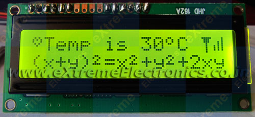 |
Fig: Custom Char Demo ! See the heart and other symbols? |
Going Graphical ?
If you have more sophisticated display requirement then you may go for Graphical LCDs (GLCD) they can render graphics like Icons and bitmaps (images), support graphic primitives like line,circle, rectangle etc. Also they can draw text in different fonts and sizes. That means 100% fun! And they are cheap and very easy to get started (thanks to ProGFX.org). We have some beginners tutorials for it too. So why waiting? Go Graphical!
Have fun and don’t forget to bookmark this page. If you think this tutorial has helped you please post a comment.
Author
Avinash Gupta
Thanks for the tutorials n carry on… rest assured there are many people learning something from them! Can’t wait for the next articles!
Pingback: Using the Analog To Digital Converter. | eXtreme Electronics
Pingback: Using IR remote with AVR MCUs | eXtreme Electronics
Why is this lcd display being operated using 2 ports? Can it be set up to use only one?
I believe so:
//Line1 = 0x80
//Line2 = 0xC0
//Line3 = 0x94
//Line4 = 0xD4
Example:
LCDWriteString(0x80,”Text1″); //Line 1 text
LCDWriteString(0xC0,”Text2″); //Line 2 text
LCDWriteString(0x94,”Text3″); //Line 3 text
LCDWriteString(0xD4,”Text4″); //Line 4 text
Oops i’m an idiot. This site was very helpful, THANKS!
wonderful site, but your css-layout seems to be broken on
https://extremeelectronics.co.in/avr-tutorials/using-lcd-module-with-avrs/
(tables are not displayed correctly!)
@bla
Hi,
Thanks for reporting! Ya the content just now looks horrible!!! Yesterday I applied a new theme and due to lack of time cannot complete it properly.
I will clean everything soon.
@bla
I have edited the page, now the layout is much better and readable.
Pingback: Interfacing Temperature Sensor with AVR Microcontrollers - LM35 | eXtreme Electronics
Hi,
I managed to burn the hex file onto the MCu but im unable to see the output on the LCD. how can i fix this?
Check the following
1)The Code is for ATmega8 MCU
2) See the connection section in lcd.h file and confirm that they are same as the physical connection u made.
3)Connect a 10K POT between Vcc and GND and the centre PIN to PIN 3 of LCD (contrast) and adjust it till chars are visible. But as in circuit above u can also GND this PIN.
4)Pls check all connection
We can discuss further on this in forum
http://forum.extremeelectronics.co.in/viewforum.php?f=2
Thanks for the Tutorials… I need a help that how the data trnasmitted to LCD and where the data is stored to display on the LCD.Pls kindly clear my doubt by explaining the transfer of data to LCD…
Hello Pooja
🙂
To know the internals pls explore the source code and see this link
http://forum.extremeelectronics.co.in/viewtopic.php?f=3&t=9
Hi.
Thanks! After trying out like 6 other lcd libraries out there on my ATMEGA-128 @ 16Mhz, yours is the only one I could get to work! Thanks!
Hello Jonathan,
🙂
Nice to meet you! I am happy that my codes are helping peoples.
can you write me a code
@Benjamin,
If you can pay.
Avinash: Great library! Easy to use and modify. A question, however: How can I print the value of a variable, such as the character contained in the serial UDR register, to the LCD?
Hello Levitis,
Yes you can print the content of a varriable.
1)char type : USE function LCDData(char_varriable);
2)int type see: LCDWriteInt() & LCDWriteIntXY() functions.
🙂 Have a nice day !
Thank you very much!
How can i configure the library file to use it with a 4 lines 20 characters LCS?Please any help.
Hello,
The 4 line modules are actually 2 LCD module pack into one.
I think they are accessed like two different modules. They have 2 HD44780 controllers in them.
Can u explain the functions that you wrote in the lcd.h file..
It helped me a lot, thanks. You are doing a good job 😉
Dear Avinash,
When i am compling your code it is giving 5 errors and it is saying that “lcd.h : no such file or directory exist” what should i do…
Pingback: Easy 24C I2C Serial EEPROM Interfacing with AVR Microcontrollers | eXtreme Electronics
in this statement how to select portb(4-7) instead of 0-3?
#define LCD_DATA C //Port PC0-PC3 are connected to D4-D7
code is very useful. Thank you..
Great ideas, is there a place to elaborate on this all?
Wew..thx bro! this lib is very helpful!!! now i can working on my final project…..lol
La pagina es espectacular, soy fanatico de los AVR…
en su sitio he encontrado cosas muy buenas!!
Thanks…
Saludos desde CHILE!!!
can we do the program for LCD through WINAVR for ATMEGA16??????????????????
@SANTOSH
SO WHAT IS THE THAT LONG PAGE ABOUT ???
DON’T POST SUCH SILLY QUESTIONS!
my lcd data pins are connected to portb as
DATA 4 – PINB 4
DATA 5 – PINB 5
DATA 6 – PINB 6
DATA 7 – PINB 7
can you give the right modification in lcd.h connection
@ Sanjay
Tell me the position of RS/RW/ and E Pins
also the MCU in use
Currently you can only use LOWER NIBBLE OF A PORT (i.e. bit 0-3) for data port.
And you are trying to use higher nibble (i.e. bit 4-7) which is NOT possible.
:)Thankyou.
the pin cinfiguration is as
RS – PB.0
RW – PB.1
EN – PB.3
D0 – PB.4
D1 – PB.5
D2 – PB.6
D3 – PB.7
and working in 4bit mode
Thanks for your tutorial,
I have some question about your tutorial, I’ve been used codevision avr before, and now migrate to winavr, my LCD data port belong to PORT C4, C5, C6, C7
how to set my data port in your lcd.h ?
First of all……thank you very very much Avinash. Brilliant job with the tuts. Hats off….
I did try this out with ATmega8 and it worked A ok.
But now want to try this out with ATmega32 and the code doesnt seem to work.
Before trying it out with ATmega32 i did chance the code in lcd.h file like shown below.
But i don’t seem to get any o/p.
Can you please help and tell me why this code only works for ATmega8 and not ATmega32 ?
#define LCD_DATA C //Port PC0-PC3 are connected to D4-D7
#define LCD_E D //Enable OR strobe signal
#define LCD_E_POS PD6 //Position of enable in above port
#define LCD_RS D
#define LCD_RS_POS PD4
#define LCD_RW D
#define LCD_RW_POS PD5
@Varun
Yes it works with ATmega8/16/32 and many more. Just check the CPU speed you set. In AVR Studio Give exact CPU frequency(crystal) in actual use.
Thank tou very much Avinash.
I have tried it but it did not work. I am using AVR Studio for an ATMEGA8.
When I try to Build the project there are two errors:
“… Section .text will not fit in region text”
and
“… region text overflowed by 3506 bytes”
Please, could you help me with this?
Thank you
@Andriu,
The problem is that you have OPTIMIZATION turned off. Go to Project->Configuration and change optimization to O2. And report to me if it solved the problem. 🙂
You were right, now it is built, but nothing is written in the LCD.
It seems to write only the first line and a few seconds later, it seems to write the two lines of the LCD but there are no characters, all the points get black.
I have a 10K pot and move the contrast but it does not work. Either it is all white or all black, the characters are not printed.
In project options I have selected FREquency 12000000 Hz. Is it correct?
Thank you again for your time
Hello,
I have been trying and I can not make it work.
I have connected ENABLE at PB5, RS at PB4 and RW at PD7.
Can be there the problem? Should I connect all of them to the same port?
Thank you, Avinash
@Andriu,
What is the freq of crystal u r usin?
and tell me the details of connection (all pins)
I am using STK500 and I amtrying to make it work at 1 MHz.
I have changed in lcd.c and lcd.h: #define F_CPU 1000000UL
In Project, Configuration options, Frequency: 1000000 Hz
and when I program I select:
– Fuses: Internal RC osc 1Mhz (I have also tried Ext. Clock)
Connections:
PB0 –> data 4 (11 in LCD)
PB1 –> data 5 (12 in LCD)
PB2 –> data 6 (13 in LCD)
PB3 –> data 7 (14 in LCD)
PB4 –> RS (4 in LCD)
PB5 –> ENABLE (6 in LCD)
PD7 –> RW (5 in LCD)
The first line of the display is black and the second is white.
I have repeated the assembly with a new LCD and new cables and the same is happening again. I guess I am forgetting something.
@Andriu,
Have u edited the lcd.h file’s connection section ???
Yes, I have edited the lcd.h file. This is the text:
#ifndef F_CPU
#define F_CPU 1000000UL
#endif
…
#define LCD_DATA B //Port PB0-PB3 are connected to D4-D7
#define LCD_E B //Enable OR strobe signal
#define LCD_E_POS PB5 //Position of enable in above port
#define LCD_RS B
#define LCD_RS_POS PB4
#define LCD_RW D
#define LCD_RW_POS PD7
hey nice tutorial avinash….
if i connected the lm 35 to adc0 and humidity sensor to adc1 how to write the code for it can you help me for this
Avinash,
thank you very much. At last I managed to make it work. I do not know why (your code seems to me all right), the atmega was in an infinite loop when I called to InitLCD().
I have changed in function void LCDBusyLoop() the condition while (busy) for while(busy==0x00) to force it to leave the loop. And in main() I write
InitLCD(LS_ULINE);
LCDClear();
LCDWriteStringXY(0,0, ” “);
LCDWriteStringXY(0, 0, “Hello World”);
Somehow it works.
Again, thank you very much for the code and for your answers.
Best regards from Spain
Avinash,
Thanks a lot for your nice working Tutorial. I have become successful in LCD programming using ur files..
A little problem is that it sometimes does not want to start instantly. After switch off/on of power, it then starts….Why is that..?
Hy!
Thank you for these gresat tutorials.
I have managed to get my 2X16 LCD to work on PORT B, but I noticed that I need that port for other things(on Atmega 16).
I’ve connected the LCD to PORT C:
PC 0-3 to LCD 11-14
PC4 – RS
PC5 – RW
PC6 – E
I also edited the lcd.h as it follows:
#define LCD_DATA C //Port PC0-PC3 are connected to D4-D7
#define LCD_E C //Enable OR strobe signal
#define LCD_E_POS PC6 //Position of enable in above port
#define LCD_RS C
#define LCD_RS_POS PC4
#define LCD_RW C
#define LCD_RW_POS PC5
The lcd doesn’t working, it shows only the first line with all points on.
I have also checked the connections with a multimeter. Everything is ok.
Please help me!
@Andrei
While using PORTC in ATmega16 you need to disable the JTAG functionality which is by default enabled on the ATmega16.
See that u have disabled the JTAG functionality first.
To disable the JTAG u need to change the high fuse bits…
Thanks for the respone. but it still doesn’t work.
I have disabled the JTAG option and the result is the same.
..with AVR Burn-o-mat i wrote D9 on hfuse
..and another thing, if i reset the MCU, one time lcd displays one line full oh pixels, and other time it shows 2 lines. I don’t know what is the problem.
@Andrei
please tell ur gmail id.
R u able to do that with other ports
I have only an yahoo account bboyandru
and yes, with port B it worked
It ain’t working anymore, neither with PORT B 🙁
Yes!!!!
It is working, on PORTC too, thank you so much for your time.
The problem was that in lcd.c I have modified LCDBusyLoop function as mentioned above ( while(busy==0×00) ). I replaced with while(busy) as Avinash wrote first and is working. And with PORT C the problem was with disabling JTAG.
Thank you so much!
Hey just wanted to check whether the LCD display you are using uses a HD44780 controller or a KS0066 controller.
And also to check if you know whether there are any differences between them.
Thanks
@Trandy
They are HD44780 based
hi thanks a lot buddy!
I have a small question please, I did all the connections properly and compiled your sample program successfully. I also accordingly changed the 12000000UL to 16000000UL in both the c file and the header file (libraries) since I’m using an external 16MHz crystal.
My problem is that it shows all black on the first line in each box. I have no idea why, any ideas?
thanks man 😛
oh btw im using the atmega32. This is for a uni project im working on so it needs an lcd and I was lucky I found yours :)thank you!
Hey Man (Krishan),
Do u think you can use the external crystal by just hooking the crystal to MCU? Also pls see above comments, u need to disable JTAG to use PORTC on ATmega32
Hi!
The external crystal is connected to the mcu. Yes sure thanks I’ll disable the JTAG on the atmega32 via the fuse bits and see what happens.
btw that was a fast reply 😛
Dude you are the best! it works!! The jtag was the issue 😛
Also I just want to confirm in your tutorial it says that: LCDWriteInt(int val,unsigned int field_length);
val is a integer value, whatever that may be, will be displayed. So if I had a global value named ‘distance’ instead of ‘val’ (since my project calculates distance), whatever value that the program calculates and stores into distance it would be displayed on the lcd.
Pingback: AVR Project – Relay Timer with ATmega8 AVR MCU | eXtreme Electronics
how do i add header files in case i m using winavr(programmers notepad n makefile) instead of Avrstudio..??
@Krishna No need to add headers files just put then project dir
Nice Tutorial.Well i am one of those who has this problem, especially with portC and my jtag fuse is disabled but the problem remains.I have atmega32 with external crystal 8 mhz and using AVRSTUDIO 4 .I am sure that i have disabled JTAG fuse bit but if i am wrong here are my fuse bits : hbits are 0xD9 and lowbits 0xFD.I need immediately to use portc for Lcd only!With other ports there are no problems, its working well!Any help and reply if possible…
Thanks
@Kostas
Use High Fuse = 0xC9 and Low Fuse = 0xFF
hey buddy! just would like to say many thanks for the libraries, they work great.
I just have a question please. Here’s a small snippet of code.
int main(void)
{
// Initialize the LCD
InitLCD(LS_BLINK|LS_ULINE);
//Clear the screen
LCDClear();
welcome(); // Welcome the user to the device
// Initialization code here for the timers and some variables
sei(); // Enable global interrupts
for(;;)
{
// Would like some code to run here
}
return 0;
}
My question is that the function welcome() displays my name, and then the name of the project perfectly, however after that no code in the infinite for(;;) loop runs. I would liked to have some calculation routine there however if the LCD libraries are enabled (that is, not commented out) the for(;;) loop and the code inside it won’t run. However if the libraries initialization are commented out then access to the for(;;) loop is restored and code in it runs.
I noticed this on the built-in debugging (im using atmega32 with the simulator also being being atmega32 within avrstudio). Also in practice, the code that was in the for(;;) routine never ran.
During debugging, when the simulator comes to the line:
InitLCD(LS_BLINK|LS_ULINE); <–
AVRStudio then switches to LCD.c towards start of the line:
initLCD(unint8_t style)
Then when F11 is pressed again to resume debugging it goes to the delay_basic.h file to the line:
_delay_loop+_2(uint16_6 __count)
Then when F11 is pressed again it goes to the delay.h line to the _delay_ms(double_ms) function. It’s here that it is forever stuck in the while loop:
while(__ticks)
{
_delay_loop_2((F_CPU)/4e3) / 10);
_ticks–;
{
So I think this is probably the reason why any code in the for(;;) routine in the main function never runs. Any ideas? Please help thank you…
PS: Sorry for bridging the question over 3 posts, I didn’t think it would allow the post to be all in one.
hii
avinash thanks for the tutorial..
i m trying this api for atmega16l..
what should be the frequency of mcu and what will be the fuse bits corresponding to that frequency..
hi
thnx for your gr8 tut
ihave some problem
the pin cinfiguration I used is as
RS – PB.0
RW – PB.1
EN – PB.3
D0 – PB.4
D1 – PB.5
D2 – PB.6
D3 – PB.7
and working in 4bit mode
where do i have to make changes in the lcd.h file for the data pins and what should i write
plz urgent
Hmm….Ainstain said that two things are infinite: the universe and human stupidity; and I’m not sure about the universe.I fixed it ,it was in front of my eyes, hardware problem.The DIP connector i used for PORTC it was backwards etc:Port0-port1….ground-Vcc for the other ports and for portC were Port7-Port6…ground-Vcc.Well i deserve the title “the ..rk of the week”:P.Thanks for your quick answer Avinash and keep your great work going on and on.
hey avinash i want to print the degree symbol on the lcd..plz could you help me wid that..thanking..waiting for your reply…
Hey avinash…..Your lib worked great on 16×2 LCD…..i was wondering whether i cud use the same lib for a 16×4 LCD module…
why I cant access the forum.extreem electronics
@Monang
Some hacker attacked the server and injected malicious code in it so I have to stop the site. I will restart it once every thing is corrected. It was very horrible experience.
Sir,
Your way of teaching AVR is awesome…. I did not read any text book but understood AVR and able to use it for my projects.
I have problem with the LCD library that you have provided on the website. My problem is my LCD is connected to port B and I want to change the library code for it. The LCD uses databits D0-D3. The connections are made as follows-
RS-PB.0
RW-PB.1
EN-PB.3
D0-PB.4
D1-PB.5
D2-PB.6
D3-PB.7
In the library code it is given that Px.0-Px.3 should be connected to D4-D7 of LCD. But my development board does not allow that. So please tell me how to connect PB.4-PB.7 pins of AVR to LCD’s D0-D3 data pins.
Thank You
Pingback: Interfacing DS1307 RTC Chip with AVR Microcontroller | eXtreme Electronics
HI Avinash,
This tutorial is of great use.
I have a small question, I am trying to display characters on lcd sent via serial port. But when i send ‘a’, lcd displays ’97’. Can you tell me how to convert ASCII to letter to display ‘a’.
My code is:
data = USARTReadChar(); //reads the letter
itoa(data,buf,16); //converts to ASCII
send_lcd_str(buf); //this function displays only strings
Thanks.
@Jimi
The code will be like this
char data[2];
data[0] = USARTReadChar(); //reads the letter
data[1]=’\0′;
send_lcd_str(data); //this function displays only strings
Hey avinash…..Your lib worked great on 16×2 LCD…..i was wondering whether i cud use the same lib for a 16×4 LCD module…
Avinash,
I was hoping you could elaborate more on your comments below. I would also like to use these libraries to control a 4X20 LCD and don’t really know where to start in editing the libraries.
Avinash Says:
Hello,
The 4 line modules are actually 2 LCD module pack into one.
I think they are accessed like two different modules. They have 2 HD44780 controllers in them.
February 20th, 2009 at 12:45 pm
hello avinash,
your library is very easy to us,i use it for interfacing 16*2 lcd module but for 16*4 its not working.plz help to use it with 16*4 .
Dear Avinash,
This page and your code was very helpful. I’ve got an LCD module working on PORTB of an ATTiny2313. Can you help with the following. I would like to turn the cursor off. I looked up the codes for the HD44780 and found the cursor off code. I tried adding the following to lcd.h
#define LS_NONE 0B00000000
Then I initialised the lcd with InitLCD(LS_NONE);
I still get both a flashing and underlined cursor. Is there any way to turn it off?
@Ian
I also tried to give command as per the datasheet but could not turn off the cursor. I don’t know whats the problem. If you find a solution please share with me. Thanks 🙂
Hello Avinash,
You said you have two different codes for ATMega8 and ATMega16/32
I am using ATMega16 so can you give the code or I can use ATMega8 code with some changes . I have already made some changes as per your tutorial. But I am using same lcd.c, “lcd.h” and “myutils.h file with only these changes:
LCD CONNECTIONS
*************************************************/
#define LCD_DATA B //Port PB0-PB3 are connected to D4-D7
#define LCD_E B //Enable OR strobe signal
#define LCD_E_POS PB4 //Position of enable in above port
#define LCD_RS C
#define LCD_RS_POS PC7
#define LCD_RW C
#define LCD_RW_POS PC6
Is it correct or I need to change something else also
hey avinash ,
my comment is still in waiting …..would you please accept it.
Please help my program is not working .
Hey I am sorry avinash , m new in this field ….but I didnt found ATMega16 code in your tutorial ….as you said you have written codes for ATMega16 also . can you please send me that link .
If there is no code in your tutorial then is it possible to make some changes in ATMega8 code to use in ATmega16.
thanking you
Seema
Hi, great website and library
I found that cursor does’t react to ULINE and NONE(as was said), so I looked at lcd datasheet, and found that function set command have to be befor.
so int the LCDInit(…) write
LCDCmd(0b00101000);//function set 4-bit,2 line 5×7 dot format
LCDCmd(0b00001100|style);//Display On
and it works perfectly
thank’s
@Sarunas
🙂
Many thanks for solving the problem. I will try it out.
Thanks, it works perfectly fine,
just infomation for loosers as I am 🙂 :
It is in lcd.c, change it from:
LCDCmd(0b00001100|style);
LCDCmd(0b00101000);
to
LCDCmd(0b00101000);
LCDCmd(0b00001100|style);
Avinash
thats really cool as your others. But is seems to me your library doesnt work for the blue lcd. its ok for the green.
Is the blue differ from green except led color?
@Rohan
It works flawlessly on BLUE LCDs too !!! I have tested with many modules.
Just use your Common Sense and you will get it working (I won’t give a silly tip so as how to use blue LCD as any one with brain can figure it out in less than 2 minute)
Hello Avinash ,
HAPPY NEW YEAR and may god you and fulfill your dreams. hey avinash I didnt found atmega16 code for LCD display . would you please help me to get a code for atmega16 . m using 2×8 and 2×16 lcd display . In your tutorial its given only for atmega8 .
thanking you
@Seema
Its for all AVR so will work with ATmega16 too !
hey avinash….
good work man…do you have any thing with LCD connected to RS-232. so that I can send data from PC to LCD.
Ritesh
ritesh Says:
hey avinash….
good work man…do you have any tutorial with LCD connected to RS-232. so that I can send data from PC to LCD.
Ritesh
Thx,it works great! Finally!
Can u tell me how to make scrolling text?
hello avinash….
thank u coz u r very helpful…
i hav interfaced 3 circuits(metal detector,natural gas detector,temperature detector) to atmega8 and this atmega8 controller is interfaced with gsm modem for sendin message to mobile phone when any 1 of the circuit o/p is positive….
i.e…when metal/gas is detected we should get sms to our mobile…but regarding temperature after 30 seconds from the time we switch on the controller,wat ever temperature is detected we should recieve sms…pls help me with program…
pb.1-r/w
pb.2-rs
pb.3-e
pb.4-db4
pb.5-db5
pb.6-db6
pb.7-db6
I need desperate help
Modifications please!
Great !!!!!!!!!!!!
sir while testing lcd i ahve this problem
my file name is sa.c
make: *** No rule to make target `myutils.o’, needed by `sa.elf’. Stop.
Build failed with 1 errors and 2 warnings…
my file name is satya.c
i have this problem too………
make: *** No rule to make target `myutils.o’, needed by `satya.elf’. Stop.
Build failed with 1 errors and 2 warnings…
sir i got that
i solved my problem
thnk u a lot………..
go ahead …….BEST OF LUCK
It works fine,but I want to move the 2’nd row from right to left,Can u tell me the way to do this?
Can u please upload the code for using custom characters for 4-bit lcd interfacing.It’ll be very helpful to us.
Hey, I would like to know how to enable the backlight. I am using a 4×20 LCD. I burned the sample codes into the Atmega8 and it works fine. But I am unclear of one thing, do we have to change anything if I use a 4×20 instead of a 2×16? As Avinash mentioned that it is actually two LCD modules in one. I am still not good enough to write my own codes. Any suggestion on learning C for AVR? Thanks.
nice tutorial, and your library was also cool.
I want to ask how to display float values in LCD like 4.7 or 23.665. Which kind of datatype shall we choose? ufloat16_t??
Best library I have used so far…. extreme thanks to author Avinash Gupta :)…
@Mayank: You can write floating value using this library too..just add
void LCDWritefloat(double val,unsigned int flbp,unsigned int flap)
{
uint16_t y=0;
uint8_t x;
double f=0.0;
f = val;
y = f;
f -= y;
for(x=0;x<flap;x++)
f *=10;
LCDWriteInt(y,flbp);
LCDWriteString(".");
y = f;
LCDWriteInt(y,flap);
}
val : floating data, double type here..
flbp : field length before point
flap : field length after point
for example
LCDWritefloat(68.198,3,2);
will print 068.19
@Nahian Rahman
Thank you very much… Let me try it out…
hi avinash!
i was using your LCD library after successfully using your ISR based timer tutorial.
i got a problem though… no text is displaying on my 16×2 LCD. only rectangular blocks on the top row. I am using the following pins and edited the lcd.h to reflect the pins i am using . Also changed the F_CPU to my crystal frequency which 4MHz. I changed both in lcd.c and lcd.h I am using ATMEGA32L
#define LCD_DATA C //Port PC0-PC3 are connected to D4-D7
#define LCD_E C //Enable OR strobe signal
#define LCD_E_POS PC7 //Position of enable in above port
#define LCD_RS C
#define LCD_RS_POS PC5
#define LCD_RW C
#define LCD_RW_POS PC6
thank you for any tips and help how to solve it.
again many thanks
neil ablang/ manila, philippines
@ neil ablang….
sounds like u didnt disable JTAG…To use PORTC of mega32/16 u must disable jtag……. to disable it write
MCUCSR |= (1<<JTD);
MCUCSR |= (1<<JTD);
at the top ur port initialization……
@Nahian Rahman
i did as you have suggested. thanks . it has two lines of rectangular blocks now. my problem now is only percent is displaying on the first block on the first line (0,0 coordinate). my strings are not being printed.
many thanks for any help
cheers
@ neil ablang
Once u able to interface it with mega8, its a matter of patience & carefulness to deal it with other mega ic’s.
1) PC4 doesnt have any connection according to ur code. check it on circuit; as well as other connections again…
2)where u place MCUCSR……. write ur main program here….
3) LCDWriteStringXY(x,y,msg); make sure u wrote msg in double cottoned…not single (“msg” , not ‘msg’)..
@Nahian Rahman
thanks for the help nahian.
yes PC4 is not connected ..thats pin 26 on 40 pin PDIP atmega32L.
i checked all my cables and their connections. all checked for continuity. My LCD data sheet is found here : http://forums.parallax.com/forums/attach.aspx?a=19747
i also tried modifying the high fuse bits for atmega32 from 0x99 to 0xD9 just to disable JTAG permanently.
The MCUCSR is set on the main() function, before calling InitLCD().
the problem still persists. no characters displayed but at least there is a blinking i see. so there is hope
again many thanks for any help
@Neil,
Whats the crystal being used? I mean its frequency. Also please move the discussion from this page to the forum
http://forum.extremeelectronics.co.in/viewforum.php?f=2
hello Avinash/Nahian Rahman
its working now. the problem was in the compile process.. being my makefile is written by me and works for my other programs but it does work with the LCD library. So I modified my compile flags to include the following when linking the object files : -Wl,-Map,main.map,–cref
and that made it work.. thank you so much. i have tried other LCD libraries too.. the one peter fleury also did not work at first.. once the extra compile flags were added.. it also worked.
Pingback: Interfacing MMA7260 Triple Axis Accelerometer with ATmega32 - AVR Tutorial | eXtreme Electronics
this tutorial is good…..:)
best library ever, but can someone help me to use it with 4×16 lcd module, i dont know what to modify or what to add to use it with 4×16.
tnx
Daniel
@Daniel,
I have the improved version ready but I have not still made it public. I will support 20×4 and 16×4 modules, custom chars, more flexible pin mapping etc.
Hi Av..
Uhm.. help?
I damaged an atmega32 trying to disable jtag. Do you know how to resurrect this chip?
Also.. how to disable JTAG using “avrdude” with an atmega32?
@wlevis,
May be you chip is alive, just connect a crystal at the XTAL pins and try.
@wlewis
to make live for some dead chips:
http://diy.elektroda.eu/atmega-fusebit-doctor-hvpp/
Thanks. Meanwhile.. can somebody tell me how to disable JTAG using avrdude? Actually it is alive.. but the device signature is completely out of wack. Have been unable to revive it using the defaults.. even tried 0x3F unlock.
Well.. got this to work on PORTD. Still…
Still.. as I want to use PORTC I need to know:
1) how to disable JTAG using avrdude
2) how to revive chips using avrdude
3) A library tutorial
4) An eeprom tutorial
ATmega32 REVIVED!
Simplicity itself: used a 12mhz xtal instead of the 16mhz I was using and burned the fuses set to default. Will now try to disable JTAG.
SUCCESS!
Lcd Library now running on PORTC. yEs! Feels good. Ok.. for those using avrdude directly.. to disable JTAG use:
avrdude -p m32 -b 19200 -P COM3 -c avrisp -V -F -e -u -U lock:w:0x3F:m -U lfuse:w:0xe1:m -U hfuse:w:0xd9:m
Btw.. Im using the arduino avrisp programmer (found in arduino samples) on an atmega328p chip. Also using a usb to serial cable. Which brings to my next request.. hee hee..
An Attiny mkii programmer tutorial oh Yea.. Avinash you da man!
I cant wait till we get to video interpretation and laser for Robotics mapping. Im so excited im gonna pee.. haha.
Ok.. tested the lcd.h a bit. Your lib incorrectly assumes my 20×4 is a 20×2 lcd. Looked thru your lib for a way to tell it my lcd is 20×4 but if its there its not obvious. So now I have to examine the lib to find a way to implement this option. Of course, I dont mind, as I will learn. Still.. why rebuild the wheel? Given the excellence of your tutorials I was expecting a library on par with the arduino lcd library which is “superb” and “thorough”. Please use Arduino as a reference point in the future. Hmmmm.
@Av
Is this where I tell the lib Im using a 4 line lcd? Where do I get that information? Should i be posting in your forum?
lib.h >>
LCDCmd(0b00001100|style);//Display On
LCDCmd(0b00101000);//function set 4-bit,2 line 5×7 dot format
@wLewis,
I will mail you 20×4 lcd support by evening.
sir,can u please upload the custom characters tutorial for
a 16×2 lcd (4-wire)module.I have been waiting for it long time.
It would be great help for me,sir,Thank you.
@Av..
Hey Av.. wheres that 20×4 support?
hmmm, there is something tricky with this support, when i try to display a longer than 24 character string on one line with scrolling option of text on, i observed that it only scrolls first 24 characters and the next ones on the second line in the limit of another 24 chars, and if the string is longer than 48 chars, what is over 48 is not showed, can you confirm this issue please?
Avrdude code for atmega32 // 16mhz crystal // Jtag disabled.
avrdude -p m32 -b 19200 -P COM3 -c avrisp -V -F -e -u -U lock:w:0x3F:m -U lfuse:w:0xef:m -U hfuse:w:0xd9:m
I have to rectify, that is not an issue, instead is a LCD’s McU limitation in locations of memory available for each display line, and there are 40 characters, not 24 as i said above.
Hello Avinash,
Do you have any serial LCD with you?
Vinod
@Vinod,
Sorry we don’t have serial LCDs
Pingback: Interfacing RFID Reader with AVR MCUs - AVR Tutorial | eXtreme Electronics
Pingback: Interfacing Ultrasonic Rangefinder with AVR MCUs | eXtreme Electronics
i have been following ur tutorials..
i need information about why we generally use 4 bit mode(4 data lines+3 select lines) operations in programming with lcd
though we have 8 data lines .. why dont we use all data lines instead we use only four..
is thest any difference in operation..please clarify my doubt though it seems simple..
@Phani,
If I say you the cost of LCD is Rs 135 but you may also pay me Rs 270 if you like, then how much would you pay ?
The 4bit mode is bit difficult to program compared to 8 bit mode, but the reward is saving of 4 i/o pins !!! Got it?
Got it..!!as we are more interested in reducing no. of i/o pins we have shifted to 4 bit mode..with a slight change in program compared to 8 bit mode..got it sir..!!:) thank you..:)thanks for clarifying my doubt though its very basic doubt..:)
Pingback: 4x3 4x4 Matrix Keypad Interface with Atmel AVR Microcontrollers | eXtreme Electronics
I’m finding sometimes when I power it up the lcd module does not display characters. It’s like the lCD does not get properly initialized. I noticed if I use a longer power wire it happens more frequently. I’ve tried adjusting the initial power on delay before the init but it doesn’t make a difference. Any ideas what could cause this?
I think I’ve got it fixed. I doubled all the delays in the LCD busy loop function. Now it works on every powerup. Not sure if this is because I am using an atmega48?
void LCDBusyLoop()
{
//This function waits till lcd is BUSY
uint8_t busy,status=0x00,temp;
//Change Port to input type because we are reading data
LCD_DATA_DDR&=(~(0x0f<>LCD_DATA_POS);
status=status<>LCD_DATA_POS);
temp&=0x0F;
status=status|temp;
busy=status & 0b10000000;
_delay_us(1); //0.5
CLEAR_E();
_delay_us(2); //tEL def 1
}while(busy);
CLEAR_RW(); //write mode
//Change Port to output
LCD_DATA_DDR|=(0x0F<<LCD_DATA_POS);
}
hi,
Enclose you a solution for LCD 4x (20/40). All you have to do is replace the existing code with my in lcd.c
void LCDGotoXY(uint8_t x,uint8_t y){
if(x<40){
switch(y){
case 0: // Line 1
x|=0x80;
break;
case 1: // Line 2
x|=0xC0;
break;
case 2: // Line 3
x|=0x94;
break;
case 3: // Line 4
x|=0xD4;
break;
}
LCDCmd(x);
}
}
@Mihael,
Thanks.
Thamks for ur great help
Thanks for ur great help
HI,
after compiling I always get the same error “error: lcd.h: No such file or directory”
The strange thing is if I try the Sample “LCDTest” I don’t have any problems, but if I start a project for an ATmega32 with exactly the same code and adding the lcd.c, lcd.h myutils.h I always get the error explained above.
Where could the problem be?
I know that “ankit agarwal” asked the same question but it seems that it didn’t get answered yet. Hope you can help me.
Thanks for your time.
@Alex,
We would be happy to help you. But please post in the forum. Thanks!
http://forum.extremeelectronics.co.in
Pingback: AVR Project – ATmega8 based RPM Meter | eXtreme Electronics
I got a problem. I cant use the function #define LCD_DATA A because my data pin is somehow inverted after i have done the PCB , meaing that Pin 0 – D7 , Pin 1 – D6 , Pin 2 – D5, and Pin3 – D4. Please help on how to configure one data pin at a time. Thanks!
Great tutorial! helped a lot of people…
keep working, the other tuts are even better!
Thanks!
@Stefano,
Thanks (from the Author)
Hi Avinash,
I’m using the LCD in order to display the value read from the ADC module.
Is there a kind of “buffer” in the functions that write into the LCD?
I’ll post some code:
volatile char adc_val[5];
..
//ADC, ports and LCD setup and infinite loop in main
..
ISR(ADC_vect){
…
getTemperature();
…
}
getTemperature(){
…
LCDClear();
itoa(ADC,adc_val,10); //itoa adds at the end of adc_val
LCDWriteString(strcat(“ADC= “,adc_val));
_delay_ms(1000);
LCDClear();
strcpy(adc_str, “”);
…
}
here’s the problem: the first time getTemperature runs, it displays “ADC=XXX” correctly, while during the second execution it writes into the LCD this: “ADC=XXXYYY”, being YYY the second value of the ADC.
In the last instruction i try to make the string blank, but this doens’t affect the wrong behaviour.
Any ideas?
Thanks, Stefano
Hy Avinash,
I have a problem or a question… I have an LCD like this, using your configuration with portc and an external 16MHz quartz, modified the library with #define F_CPU 16000000UL i use an atmega168, and avrisp mk2 programmer, made all the settings, but fuses are killing me…
and i dont have the jtag row to enabel/disable… i have set them H.F to DC and L.F to 4e, dont work… i set them H.F. to C9 and L.F. to FF, didnt work…
Please give me an advice how to set them!!
It works!!!
Pingback: AVR Project – ATmega8 Based Smart Code Lock | eXtreme Electronics
@avinash
great job…….keep continue
i m impressed
There is sone problem with LCDWriteInt() function when we write negative number.It check for negative value whne value have gone to 0 by val/10 statement.
it should be checked in starting .I have corrected that.
LCDWriteInt()
{
char str[5]={0,0,0,0,0};
int i=4,j=0;
if(val<0)
{ val*=(-1);
LCDData('-');
}
while(val)
{
str[i]=val%10;
val=val/10;
i–;
}
if(field_length==-1)
while(str[j]==0) j++;
else
j=5-field_length;
for(i=j;i<5;i++)
{
LCDData(48+str[i]);
}
}
@Sanjay.
That’s right. I left as a homework for the user.
hello
how to make a program that ignores the RW pin signal, because the LCD is still only displaying data. On the LCD RW pin is always tied to GND, which means that the LCD display mode.
I enclose a further correction codes for data display on the LCD with 4×20
void LCDGotoXY(uint8_t x,uint8_t y){
if(x<40){
switch(y){
case 0: // Line 1
x+=0x80;
break;
case 1: //Line 2
x+=0xC0;
break;
case 2: //Line 3
x+=0x94;
break;
case 3: //Line 4
x+=0xD4;
break;
}
LCDCmd(x);
}
}
Sir,
How can we display smileys or say write in hindi on a simple 16*2 lcd in avr using bitmapping??
Thanks in advance,
Manan
Hi Avinash,
Thats an awesome tutorial. It worked for me with ATMega16 and using the given lcd library. Now I want to use an ATTiny 2313 to do the same project and to run the same sample program. I made the necessary changes in lcd.h but it is not working. I just see all black boxes on the first line. Could u help?? Thanx in advance.
this is very help ful:)
@Avinash Thanks very much for your generous release of the code!
Re posts 86/87, Difficulty in turning off flashing and underlined cursor…
It works here ok using the data sheet but after initialization!
ex:
InitLCD(0);
LCDCmd(0x0C); //get rid of U_blink and cursor
//or 0b00001100; of course
I think there is something wrong in using this with
AVR Studio 5
these are error generated on compile, project name ETako!
***
Error 2 ETako.elf section `.text’ will not fit in region `text’ D:\Users\Armen\Documents\AVRStudio\ETako\ETako\Debug 1 1 ETako
Error 3 region `text’ overflowed by 5006 bytes D:\Users\Armen\Documents\AVRStudio\ETako\ETako\Debug 1 1 ETako
@Armen,
This is a common error. That means the output code cannot be put into available flash memory.
From Project menu Goto ETako! Properties (Alt + F7) then goto toolchain tab.
AVR/GNU C Compiler->Optimization
then set Optimization level (-O2)
Then clean and build the project(Ctrl+Alt+F7).
Thank you so much!
Will you explain optimization factors? like between most & more, and why not to use most always?
I can not understand what this has to do with optimization? as you said, since overflow means not enough space for Flash/FlashPage while compiling, I think this is a pre-build error also when you compile as release mode, everything works just fine.
in release mode. which works!
tnx again.
i have no questions to ask every think is best
i don’t know any think before ur website
but i did my big project
about
2 dc motors
3 servo motors
4 pwm
3 ADC
4 relays
1 LCD
3 i/o
all are by PC controlled robot
thanks for every think
about your components are cheep best then but less components are available
the best AVR website
@Sai Krishna
Thanks !!!
robokits have more components
but no avr tutorials
u have best tutorials try for all components by u
because we are waiting for
it will be cheaper with u i think then any another
Great libray, very intuitive to use!
@Yossarian
Thanks!
how to turn off cursor? it blinks every time.
@Rashad,
One idea is to move the cursor off screen so that it is not visible. Like LCDGotoXY(17,0)
x=17 is off screen for a 16×2 module.
You can turn off the LCD cursor the next way.
First add in lcd.h this line:
*************************************
#define LS_OFF 0B00001100
**********************************
Which turns the LCD ON and the cursor off
Then add in your LCDTest.c this line:
**********************************
InitLCD(LS_OFF);
**********************************
This selects the cursor to be turned off and stops LS_BLINK and LS_ULINE
Hope this helps!
will be lcd library improevd? are you going to add new command for lcd
@Rashad
Can you suggest some required improvements?
hi.I have writed small program to send UART messagesto LCD and send mesage back to uart terminal.my message returns to terminal but i can not display it on LCD please help.small part of me code.thanks
void main()
{
unsigned char data;
USARTInit(38); //UBRR = 38
InitLCD(LS_ULINE); //Initialize LCD module
LCDClear(); //Clear the screen
LCDWriteString(“FARSAJIK”);
//Loop forever
while(1)
{
//Read data
data=USARTReadChar();
LCDWriteStringXY(0,1,data);
USARTWriteChar(data);
}
}
change like below and inform.
while(1)

{

//Read data

char data[2];
data[1]='\0';
data[0]=USARTReadChar();
LCDWriteStringXY(0,1,data);
USARTWriteChar(data);
}
}
it doesnt work.
thanx a lot for the tutorial
my lcd is working but light of the lcd in not fully on..it shows very dul characters.
your tutorials are just great it helped me a lot….
my YJ1602A 16*4 lcd module has worked successfully because of your cool lcd library but isn’t working for 20*4 lcd module 2004A . Is the library made for only 1 HD44780 controlled lcds ??? because i heard 20*4 lcd module has 2 HD44780 controllers inside……..& many thanx for other tutorials too
Thanks to author for all those nice tutorials, really good.
Am having problem in using the lcd libs downloaded on Oct 10. With this lib and sample code am not able to see any characters getting printed on LCD, I took the same sample code and used the old lib it works fine. Some changes in new libs are 1.delay has been modified, 2.In all the places 0x0F is replaced with 0xF0 and vice versa 3.#define F_CPU 10000000UL is 12000000UL in new lib. My Hardware connections and port usage are same for both codes.Pls help me to solve this issue.
Thanks so much for this info. the library and the instructions you provided was really really helpful. it was also easy to understand, even for a beginner like me.
Thanks!
Sir i wanted to reverse map the data ports.. hw is this possible? for eg need to connect d4 to pd6, d5 to pd5, d6 to pd4 and d7 to pd3..
how to do this..
Hello Avinash,
I have understood your program.I am using atmega8 MCU & Atmelstudio 4.I was not able to get the output.I think I am compiling code in the wrong fashion.I have added files as you have indicated.Can you tell me how to compile multiple source files..I am attaching my main function code for reference.I used all your source & header files..help greatly appreciated
Thank you..
#include
//#include “LCD.c”
#include “lcd.h”
#include “myutils.h”
int main()
{
InitLCD(LS_BLINK | LS_ULINE);
LCDClear();
LCDWriteString(“Greentech”);
return 0;
}
Hi Avinash,
First of all, thank you for the effort, it is appreciated.
I am trying to hook up a 16×2 char LCD with a ATMEGA328P. I did the connection as you suggest for the ATMEGA328 and programmed it with the the code you provide, but with modification in lcd.h (the definition part of RS, RW, E and data pins) to match the same configuration you provide for ATMEGA328. The LCD is lit but there is nothing happening. I can’t see the messages you put in the code. I am using the STK500 dev board. In the HW setting tab, the clock freq is set to 3.6MHZ. Could you please help me out. I don’t understant why it is not working 🙁
when using for the first time, use the same hardware as shown in the tutorial! it is not possible to debug your hardware form here !
Plase… i’m request LCD libarary for ATmega16,32 ..
Thanks for u…
azizmetronet@yahoo.com
Dear sir,
I think your tutorial and the library is very helpful. I should like to ask you if I may use your library for my robotic project in a students’ technical competition?
Yours faithfully
@Matthew,
Yes you can use them
Thank you
Hye Avinash and thanks for this tutorial !!! It’s help me a lot for my project.
I have one question… I want to use my LCD display in 8bit mode like this (with atmega16):
D7 => PORTC pin 7 to D0 => PORTC pin 0
R/E/RW => No change.
What I should modify ?? Is it easy to do?
Thanks
Aurélien
PS: Merry Christmas
Nice tutorial, thanks. My first running application with Atmega32 and LCD with large number of not working before. I have tried move all pins to port D, but display doesnot works correctly. I would like to get free C port for realtime chip on my kit (http://shop.onpa.cz/?kit-evb-4.3,27) and SDA and SCL pins. I will try move them on port B on my board tomorow. Thank again. Czech Republic
other wise you may try SoftI2C
https://extremeelectronics.co.in/avr-tutorials/ds1307-i2c-rtcc-interface-using-softi2c-lib/
This is very good and easy to use lcd library.
I have 2 questions: Is there possibility to make custom characters with this library?
How can I print character which exist in lcd rom but is not available throu keyboard? Like some lcd special characters. For example degree symbol ° is not available throu keyboard, or am I wrong?
Thanks,
regards
filip
@Filip,
Nice question. Although our internal version has support, yet the public version is short on that feature.
Soon we will release the custom char supported version.
Great, I’m looking forward this new edition.
If I want to display specific character from lcd ascii table should I write
LCDWriteString(223) ?
Instead write
LCDData(96);
you can use any valid ASCII code as parameter.
Nice project, helped me a lot!
Does this library handle 16×4 or 20×4 LCD-s with HD44780 controller?
Thanks, Attila
Thanks alot for providing this much of valuable information in easy to use LCD library.In this code i made two changes i.e.,1)connected R/W pin to GND,and commented LCDBusyLoop(); 2 times one at InitLCD and second at LCDByte(); insted of busy loop function i inserted a delay 10 ms, so here i saved one M.C.U pin.
2)I connected data pins(D4,D5,D6,D7) from LCD to higher nibble at MCUport(PD4,PD5,PD6,PD7)
with some changes at InitLCD();LCDByte();,it is working good.My question is it ok eliminate reading data from L.C.D or it’s needed,
Thanks&Regards
Murali,
Waiting for your reply….
Dear Mr. Avinash
Wonderful tutorial. I have a question. In the library you define l lcd.c following:
# ifndef F_CPU
# define F_CPU 12000000UL
If I use a crystal of 4, 8 or 16Mhz working properly the LCD, simply runs less or more speed, right.
But will it affect if I let something like this and use an 8MHz crystal of handling the USART and / or I2C?
Thanks, best regards.
Hello avinash,
If I want to use a single port (like B) for all the pins of an atmega16 then what all changes do I need to make in the associated files.
sorry, i meant port B of atmega16 for the lcd pins
extreme electronic is very good for learning electronics. thanks
hai avinash,i have a doubt.will the fuse bits vary from frequency to frequency.what will be the fuse bits for 8mhz crystal?
Chock the datasheet of the mcu you are using. Its given clearly. After that, to be certain, use http://www.engbedded.com/fusecalc/
Hey,
Thanks for the tutorial,
My dev board connections to the LCD are as follows,
PD0-PD7 go to the 8 control pins
PB6 goes to Rs
PB7 goes to R/W
and PC7 goes to E,
Please can you tell me what changes i have to make to the lcd.c to get it working….
Thanks
Sethu
PS: i’m using Atmega8 and i’m interfacing the LCD to a custom made dev board
thanx man, u indians are pretty good in tutorial writing easily for beginners. thanx again man
You may say that Avinash Ji is exceptional.
Great tutorials!
They are pretty useful for my diploma project.
Can you help me with the modifications needed for the 4×20 or 4×16 LCD?
Thank you again!
Thank you again Avinash for the tutorials!
I managed to make it 20×4.
Here is what I did:
I changed void LCDGotoXY at the end of “lcd.c” with this part:
********************************************
void LCDGotoXY(uint8_t x,uint8_t y)
{
if(x<40)
{
switch(y)
{
case 0://1 line starts at 0x80(0b10000000)
x|=0b10000000;
break;
case 1://2 line starts at 0xC0(0b11000000)
x|=0b11000000;
break;
case 2://3 line starts at 0x94(0b10010100)
x|=0b10010100;
break;
case 3://4 line starts at 0xD4(0b11010100)
x|=0b11010100;
break;
}
LCDCmd(x);
}
}
********************************************
Thank you again!
Hi Razvan
Can you help me with the modifications needed for the 4×20 or 4×16 LCD?
I tried your code and still did not work. did you made any other change?
thanks
Thanks so much. It’s just what I’m looking for. And it works perfectly. Thanks again.
@Diego Thanks !
Pingback: Displaying Custom Characters on Alphanumeric LCDs | eXtreme Electronics
Can I have this article in pdf form ? want to print them 🙂
Thank you
Whoooa!
That worked right out of the box. Amazing.
Thanks!
thanks sir for the module.
I need to show on LCD a function A^A+b, where a and b are introduced with the help of an 6×4 keypad which must have 0-9 , delete, ok, reset button and 10,20 and other values. The LCD is 16×2. Help me with the code in AVR please!!!!
Hello Mr. Avinash
I wrote the exact code you wrote as in the post,included source files and header files like you said,
earlier it was giving errors such as..
lcd.h:No such file or directory
../lcdtesting.c:7: error: ‘LS_ULINE’ undeclared (first use in this function)
../lcdtesting.c:7: error: (Each undeclared identifier is reported only once
../lcdtesting.c:7: error: for each function it appears in.)
../lcdtesting.c:25: error: ‘LS_ULINE’ undeclared (first use in this function)
Please help..
@Deepanshu Lulla
Dekh boss mere ko ise logo pe bahut gussa atta, samjha !
tere ko C ata kya ??? Mere ko to nei lagta tere ko zara bhi ata!
Clearly english me compiler error de raha aur tuhje us saltana bhi nei ata.
Ja jake koi aur kaam kar !
seriously!! even i have this problem pls help what can be done!!!
i cant understand Hindi!!
Haha, I must say some of your responses are so funny. It’s so true when they say “There are no stupid questions but only stupid people.” 😀
@NotSoFunny !
Thanks ! Well said “There are no stupid questions but only stupid people.”
include all the files correctly and check,
Hi man, this library is really a god thing!!!
I’m having some troublesand need some help.
When i try to print int or characters, lcd work fine. But when i try with strings, the lcd shows much black squares as characters i try to print… I think the problem is associated with the passing argument to the function, or the way the string is saved on program memory, but i dont know.
I’m working on linux-ubuntu, can the SO, or some routine of it, have something to do?
Thanks
Boss Thanks..When you said compiler error,I got it.
Marisha,did you copy the library components into your project destination folder.
Does this library works with atmega88??
Try and say it’s work or not.
well ,i did it,but it didn’t work,so i dont know if it was my mistake or this library doesnt work on atmega88,so that’s why i asked. thanks
@Nelson
* What is your crystal frequency.
*Write the connection of lcd and atmega 88 pin.
i will check.
Can I show the output voltage in a LCD .. IF yes can U tell me please ….
This dont work on atmega88 or something is wrong.Someone help me.Thanks
Hello
I´m trying to use the LCD at max frecuency but it doesn’t work, when I work with the internal clock at 8MHz it works just fine but when I try to use the external clock at 16MHz it doesn’t work.
How can I make it work ?
Hello Diego
Use the library provided by eXtreme Electronics, it will definitely work.If you are not able to work with MAX Frequency(16MHz) then buy the ready-mate board form the store…………
http://store.extremeelectronics.co.in/
Pingback: PS2 Keyboard Interface with AVR MCU | eXtreme Electronics
Pingback: How to display message in lcd using Microcontoller ATmega8
hi avinash ,
i have a ready made atmega 32 board. in which lcd port is like that
pc0 rs
pc2 en
lcd data pin are
pc4 pc5 pc6 pc7
the RW pin is grounded in lcd port
i have used your code successfully with other port .
but in lcd port RW pin is grounded .
so how can i modified your code to use lcd with this board with RW pin grounded.
please help.
Are bhai kahan se le liya hai board?
Tere ko koi buri tarah se mamu bana diya hai!
badiya disign mein hamesa R/w pin hamesa connect rahta hai.kaun pagal design kiya hai bord ko.Ja usi se code maang!
maine bahut se code net me dekhe hai,
r/w ke bina bhi lcd ise kr sakte hai. but i am unable to understand these code completely .
check this :
http://www.pocketmagic.net/?p=447
http://www.ikalogic.com/ika-tach/
http://www.electronics-base.com/index.php/projects/complete-projects/110-avr-2×16-character-lcd-diplay-universal-code-library
yar thoda help ker do….
Mahendra net mein code search karne se aacha hai ki 16×2 lcd ka datasheet padho or samjho R/W pin kya hai or kyun use hota hai.
can any one help me in coading to display name on lcd interface with atmega32. i want to use portB.0=rs,portb.1=rw,portb.2= en and portB.4 to portB.7 to display data. m using code vision avr c compiler. plz help me in composing the code. my emailid is aki_a24@yahoo.com
#include
#include
#include “lcd.h”
void main()
{
LCDInit(0);
LCDClear();
LCDWriteString(“HELLO”);
}
i had used all lcdlib header file u have given…..
but its show 1 error … i am not able to make whts the error…
plzz
what does the error says ?
I’m using your library for lcd interfacing
as follows
#include
#include “lcd.h”
int main()
{
LCDInit(LS_BLINK|LS_ULINE);
LCDClear();
LCDWriteString(“Heloo”);
while(1);
}
it is showing errors
Error 5 atmega8LCDEE.elf section `.text’ will not fit in region `text’ E:\august_avrstudio\atmega8LCDEE\atmega8LCDEE\Debug 1 1 atmega8LCDEE
Error 6 region `text’ overflowed by 5038 bytes E:\august_avrstudio\atmega8LCDEE\atmega8LCDEE\Debug 1 1 atmega8LCDEE
Please help me
Regards
Bikash
Can you please tell me,whether you are using AVR Studio 4/5 or ATmel Studio 6 ? After that I will be able to help you.
Thank you
I’m using avr studio 5
Bikash, you are working with Atmel studio 5,then problem is with optimization setting.First of all go to project menu,then
go to properties in project menu.OR press ALT+F7.Then go to toolchain(you will find this leftside of the
screen ).Then click on (you will see this inside ).Click on ,change the
optimization level.Click on it and set it to .After that you have to rebuild the program.Go to
, click on rebuild solution or press CtrL+Alt+F7.Now you successfully get the output. I hope you understand the
process. Thank you
kindly see this for more information http://forum.extremeelectronics.co.in/index.php?topic=2509.0
Dear Avinash,
Please Provide PDF link.
Thanks in Anticipation.
Pingback: Interfacing Analog Joystick with AVR ATmega32 | eXtreme Electronics
Hi,
Thanks for this great library. 🙂
What changes should i make if i want to read multiple keys at same time. more than one keys will be pressed at a same time, and i want to read them. Thanks
i’m using MEGA32,how i need to setting the fuse bits on burner?
sir
i am new with atmega coding n hardware . i want to interface LCD and Atmega16
as per your toutorial i made connection with portD and PORTB but i m not getting any out put at lcd please help me i would be very greatful to you
@Dheeraj
Use xBoard v2.0 to learn ATmega16 and LCD Interfacing once you learn it then go about implementing in your own hardware.
http://store.extremeelectronics.co.in/xBoard-v2.0.html
i have made connection according to your lcd.h file n programed atmega16 but i am not gettig any output at lcd plz help ..
Pingback: DC Motor Control using AVR MCUs | eXtreme ElectronicseXtreme Electronics
Pingback: RF Communication Between Microcontrollers – Part IIIeXtreme Electronics
Hello,
I have a problem with your library. I want to make LCD pointer without any highlight, underline so i initialize it with LCDInit(LS_NONE).
After programming is done everything works as it should but when i power down my circuit and power it up again cursor is blinking and its unlined just like if i would initialize it with LCDInit(LS_BLINK|LS_ULINE) while i was initializing it with LCDInit(LS_NONE)
Im using your LCD libraries with LCD compatibile with HD44780, here is my main loop
int main(void)
{
LCDInit(LS_NONE);
while(1)
{
LCDClear();
ds_conv();
//DSconvTemp();
LCDWriteStringXY(2,0,tempBuf);
_delay_ms(1000);
}
}
I also tried to put LCDInit(LS_NONE) in while loop just before LCDClear but it was the same, if i powered it down/up in wrong time cursor was going back to normal.
Where i should put LCD_Init function? Or maybe is there a way to make LS_NONE default initialization cursor?
Hello,
Im using LCD library from this article and there is a problem. When i initialise LCD with LCDinit(LS_NONE) i want to have cursor not visible. Right after flashing its ok but when i power down my circuit and power it up its going back to default blinking underlined cursor. Here is my code (i also tried to place LCDinit inside while loop but its same)
int main(void)
{
LCDInit(LS_NONE);
while(1)
{
LCDClear();
ds_conv();
DSconvTemp();
LCDWriteStringXY(2,0,tempBuf);
_delay_ms(1000);
}
}
Is there a way to make cursor be invisible by default? Or maybe i place LCDInit function in wrong place?
Does anyone have same problem Or maybe someone could please check if this happen for him. Initialise your LCD with LCDinit(LS_NONE) and then see if cursor is not visible, then power circuit down and see if is back to normal or still not visible. If its wokring please post here back and place your code where you initialised LCD. Thank you
Every time after powering on, just do a reset by pressing the reset button in your development kit and the cursor will not be shown.
I had the same problem and this works fine.
i copy you code and the atmel studio send a error.
“main must return int”
i ned help.
i found error. i´m in c++ and the project is c.
TKS
Pingback: GSM Module SIM300 Interface with AVR Amega32 | eXtreme ElectronicseXtreme Electronics
Dear Sir,
is it possible, to use a 8×1-module with your lcd-library?
Sincerely
PeterS
first of all thak u for such a good project i am 11 th class student and i made this proj. by directly burning the hex file given by u but when i go to the compiling process i get 2 warnings one is
1. e:/winavr-201……../lib/gcc/avr/include/until/delay.h:85:3:warning:#warning “F_CPU not defined for ”
2. LCDTEST.C:6:WARNING return type of ‘main’ is not ‘int’
plz give the sol. of this problem
@Akshay,
For that you need to have good understanding of C.
Hi Akshay,
this is not a problem, but a info to you. A good idea is, to take the following line in your main.c sourcecode:
#define F_CPU 8000000UL /*CPU clock in Hertz*/
You must write the right frequency of your CPU in the line.
Second, your main-function should begin with a:
int main(void)
{
…..
I hope, it helps.
Cheers
Peter
hi
Can I place the translated article along with the files in my website?
which language?
persian!
Hi Avinash,
I am using your code and have connected terminals in same manner as described in your article, i am using ATMEGA328P-PU. LCD backlit gets lit but nothing gets displayed.
Please help..
Thanks,
Ujjwal Soni
@Ujjwal,
Pay us the cost and get assembled and tested hardware.
Then only we can proceed.
@Ujjwal,
at first, is your hardware correct connected? In your software you must init the LCD-module at the right way. How do you put the data witch should be displayed to the LCD? Please post the code of your program.
Cheers
Peter
Hello,
first of all,thank you for making this great library and very very good tutorials on the subject of micro-controllers.I have two question for you if you can please answer:
1.How to print a number other than integer on the LCD display (for example 25.5 or so)? What should I modify in the lcd source code?
2. How to measure temperature with LM35 and Atmega8 but to have increments in half of the degree (for example measure temperature of 18.5 degrees Celsius)? Because as I can see in your tutorial of interfacing LM35 with Atmega8 you have resolution on one degree.
Thank you!
Hi Srdjan,
1. You have to change the integer (or float) to a string.
Code-snipped:
int main(void){
char mystr[16];
double myflt1, myflt2;
myflt1 = 3.14159;
myflt2 = myflt1*5.1324;
sprintf(mystr, “%.5f”, myflt2);
LCDWriteString(mystr);
}
sprintf makes this change. This string can be displayed at the LCD. Use the function “LCDWriteString(const char *msg);” from the library.
2. Your second problem is a little bit difficulter. One idea you’ll find at
http://www.avrfreaks.net/index.php?name=PNphpBB2&file=viewtopic&t=128191
Search in Google to “atmega8” and “lm35”.
Cheers
Peter
@Peter
Thank you very much on the reply.
I tried the code you provided, but I don’t get result as expected. I have run the simulation in Proteus ,and I keep getting ? on the screen. So it doesn’t prints the decimal number I want, but just the prints ?. can you please help with this,my programing skills in C are still not very good,I am learning.
Thanks,
Srdjan
@Srdjan,
the code-snipped is ok, but I think, you must change a little bit in your Makefile. Search in the Makefile the following line:
#PRINTF_LIB = $(PRINTF_LIB_FLOAT)
Delete the “#” at the beginning of the line and save the Makefile. Here comes the whole code again:
#include <avr/io.h>

#include <stdio.h>

#include <util/delay.h>

#include "lcd.h"
char mystr[10];
double myflt1, myflt2;
int main(void)
{
LCDInit(LS_NONE);
LCDClear();
myflt1 = 3.14159;
myflt2 = myflt1*5.1324;
sprintf(mystr, "%.3f", myflt2);
LCDWriteString(mystr);
}
In the line:
sprintf(mystr, “%.3f”, myflt2);
you can define the number of decimal places.
Info: I’m working with WinAVR
Hope it helps
Peter
@Srdjan,
I see, it’s a problem to post lines with angle brackets in it. The first three lines are the normal includes with angle brackets:
#include <avr/io.h>

#include <stdio.h>

#include <util/delay.h>
Cheers
Peter
@PeterS,
I would like to thank you for helping me with this.I didn’t respond right away because, I wanted to familiarize myself closer with WinAVR and makefile generation. Yes, you were right, the problem was in configuration of printf in the makefile. I generated the makefile again with the WinAVR mfile application, and with it a compiled your code, and run the ISIS simulation. Everything works like a charm now.
Thank again,
Cheers,
Srdjan
Hello Srdjan,
thank you for your reply. It makes me happy 🙂
If I can help you again, let me know.
Cheers
Peter
is i can print floating values such as 0.8
0.095 etc? how
Hi Justin,
yes it’s possible. I meen it’s the same problem as I described a few post earlier. Look at my answer to Srdjan at April 12th and April 13th.
Cheers
Peter
Pingback: Setup and Use of LCD Library for PIC |eXtreme Electronics
hi..
i got the error “make: *** No rule to make target `myutils.o’, needed by `lcd.elf’. Stop.
”
can anyone tell me how to fix this problem.
@Ankit,
Yes the problem is NOT paying attention to details.
You have added myutils.h to source file section in place of header file section.
thanx dude
its still creating prblem…….
what can i do to fix it?
Post in our forum.
@Ankit:
simple question from me: Do you have a file named “Makefile” in your project-folder? Your question sounds like the compiler finds no Makefile.
CU
PeterS
How I can get rid of cursor and blinking? Nothing helps 🙁
Hello, thank you very much for all the tutorials. i have been using your lcd library for my 16×2 lcd projects and it works perfectly fine. However, i just recently tried it on my 20×4 lcd but is isn’t working. nothing is displayed on the screen save the 1st and 3rd lines. I have tried to fix it but with no success. Please what am I missing. I am anticipating help from anybody who have successfully tried it. Thank you
You need to send twice the following command
for 20×4 LCD.
//function set 4-bit,2 line 5×7 dot format
LCDCmd(0b00101000);
@ Murali
thanks, it worked but only when I set the fuse bit to 1MHz internal (hfuse 0xd9, lfuse 0xe1)oscillator. when I set it to 16MHz (high fuse 0xc9 lw fuse 0xee) it doesn’t work. I’m still checking for the reason though
Finally, I got it. thank you
Pingback: Ultrasonic Rangefinder HC-SR04 Interfacing with ATmega8 |eXtreme Electronics
Pingback: AVR Project – ATmega8 Based Smart Code Lock | Sistem Komputer
Hi! Awesome article. Thanks a lot for efforts and sharing with beginners. In the sources everything seems to be clear, but some there are comments I cant get, for example, tAS, tDA, tEL, tEH (google couldnt find anything)… What do they mean (smth connected with lines stabilization, but what exactly)? And why do we always have to wait 0.5 – 1 us after each operation with ports etc?
Hey what is the crystal value to be used for atmega8.
I have set it to 1Mhz but my lcd displays only black boxes on the first line and blank second line.
Please reply soon
Hi satish,
1 MHz is ok. It sounds, that your LCD is not correctly initialised. Please take one of the demo-programs from Avinash and test it again. It works really 🙂 Check the wireing. This is the base for correct working.
Greetings
Peter
The “.hex” file that comes with the LCDTESTM8 archive works fine, but if I take the LCDTESTM8.c souce file, and compile it, if I write the resulted “.hex” file, it will work the same, but everything scroll from right to left, something like you would decrement the LCD’s X and Y positions. I don’t know how to explain it. I tried to let just the Initialisation, clear screen an LCDWriteString(“with some text in here”), and the result is the same. It run out of the screen from right to left, and then dissapear, remaining just the blinking cursor. Can anybody help me?
I solved it! 😀 I had to define the external clock frequency in the “lcd.c” and “lcd.h” files. 😀 Great tutorial by the way!
Hi Avinash,
Somehow in the LCDTESTM8-files the blinking and underline cursor seems to come back, when LCDWriteIntXY(….) is used. Can’t find the error. But maybe the LCDBusyLoop causes this problem to my clone LCD.
But anyhow the code very is useful. Although I don’t like to use the extra signal LCD_RW, because you lose one pin on the ATMEGA8. Thanks for this tutorial, it was very helpful to get on with my projects and learn about AVR Studio 4 and ATMEGA8 MCU programming. I like the fixed formatting on the integer-variable. In many examples with other MCUs (PIC’s) the RW is fixed to ground and there is no need to use the LCDbBusyLoop, because of using appropriate delays.
Greetings Jack.
This code is very solid, really thanks for the tutorial and sharings!
@YEW TZE EE
Thank you 🙂
how can i get floating value in lcd???
Hi Sir Avinash,
I am using [AVR Studio4, eXtreme burner, & Ur “USV AVR programmer”]. Ur lcd demo works OK when I “burn” ur downloaded HEX file from this site for atmega8, but my own hex file created using Ur above C codes does not work, though it is successfully build. Pl. suggest what could be wrong?…..
…..& before, AVR-4 gave errors regarding…regarding (custom_char.h) file -does not exist, so I copied this file in (project folder) & in (header file) section, then it was “build” ok, but yet its Hex file does not work on the chip at all. Pl advice..
Hi Avinash, How do we display integer for field length more than 5?
thanks for the attention
i want write text on 0,0 location and 0.1 at a time bt 0,0 location text not blink nd 0,1 location shoud be blink. pls snd programming.
Hello,
Just wanted to say “Thank You” for your contribution, dedication and hard work.
From far-away Poland.
Hi, I am new to programming electronic components! Thanks for your tutorial!
I have some questions, please help because I am really new to it.
I want to change the pin assignments:
D4 – PD0
D5 – PD1
D6 – PD4
D7 – PD5
EN – PD6
RS – PC4
and I won’t use RW
I know there are some changes in lcd.h but I don’t know how to change the #define LCD_DATA (since the pin is not continous in one port).
Also, besides changing the pin assignments, which part should I change to let the MCU program?
If I don’t use RW, can i just delete the code related to RW?
Thanks!!
That kind of pin mapping is NOT possible.
Hey Ying,
You got any solution for your problem?
Thanks!!
Hi Avinash, I will use your LCD Code for my FYP purpose, how do I acknowledge it? Do I need a permission?
Thanks for the attention!!
@YEW TZE EE
Yes, in your project details you need to tell that you are using this library!
Also need to mail me the soft copy of the project report. And the details about your project, your self and your collage.
Sure, I am in The University of Hong Kong, from Malaysia, really thanks for the reply!!
hi.. can any one pls help me out how to use lcd display with atmega32
@Nagraj GS,
Hello,
Yes sure we can help and get you stared with LCDs in few hours.
You just need to take a neat and clean (I mean a systematic path)
First you need to get a standard set of hardware.
If you agree please tell us.
Dear Avinash I face a problem. I cannot print a charecter on 16*2 lcd using ur lcd library. pl. help me. I already try with LCDData() it donot show the actual char. pl help me. thanks.
@Biplab,
If you are NOT able to do it yourself from the information given above. We can help you on personal basis but you have to pay consulting charges. If you are interested please contact us.
Thank you,
Hi Avinash,
I am done with my FYP thesis. What is your email? I will send you my thesis as promised.
Thanks for the attention.
my email is: me at avinashgupta dot com
Hi Avinash,
I cannot send email to me@avinashgutpa.com, please give a accessible email.
It is
me@avinashgupta.com not what you have spelled!
How can the LCD be used to display decimal numbers like 1.23
Thank you for this tutorial and library, I use it everyday
Thanks
I have a new Atmega8A chip and I don’t know how to program its fuse-bits. I found a lot of variants on internet and I used one that it seems to work. I made a “test circuit” with a blinking LED with delay of 1000ms. With the fuse-bits combination that I finaly found on the internet it seems to work ok for the LED, because the delay really is one second. But it doesn’t seems to work with the LCD. I need someone to tell me what combination of fuse-bits I must use to make the micu work ok. I have to mention that I use PonyProg to program my fuse-bits and I need a combination to work for an external 16MHz clock. Please help me, I already broke an mcu trying combinations of fusebits from the internet.
Sorry for my english..
C:\WinAVR-20100110\avr\bin\display\default/../display.c:6: undefined reference to `LCDWritestringXY’
..this is the error being displayed while building the program…progam is
#include
#include”lcd.h”
void main()
{
LCDClear();
LCDWritestringXY(1,1,”hello”);
}
cant build a simple program ..please help…
I am a final year student doing a project about RFID bus pass system.when a user requires a card with an RFID tag and the system should be able to deduct some amount from the users account and then display on an LCD display if the user is allowed access or not. i am requesting your help on the coding of this system.i am using atmega 328p microcontroller and the coding will be in c language. you can get me through the above mail.I will highly appreciate your help
Hi guys! First of all this tutorial is very helpful, so – Thanks’!!
I have a question about the function LCDClear(); which is working with any issues on my Atmega8, but I need to clear only one row in the LCD, or even better – only few symbols.
I want to do this because the LCD shows some parameters, which are static, and their values, which are updating every second or less. So I want to clear only the values but not the static names of parameters.
If it wasn’t clear, I’ll give an example. If I have this output on LCD:
Mode: 1
Color: black
Direction: UP
Battery: 100%
so I want to update only “1”, “black”, “UP” and “100%”. Can I do it some way?
Hi Pavel,
there is no problem. Print the changing values on the place, where they should be shown. All other things would be unchanged.
Peter
Hi Sir Avinash,
at shool we do almost our projects in CVAVR, is there a way to port this project to CVAVR because this library have advanced functions than the one included in CV.
Thanks in any way
Hi Avinash,
I have a question…Can we use LCDInit() two times in a program?….Suppose first I want to give no cursor in the display and then a Blinking cursor afterwards?….
Hi Ananyo,
of course you can use LCDInit() how often you want. But it is not necessary.
Put in your code on any position you want the line:
LCDCmd(0b00001dcb);
where
d = 1 (display on)
d = 0 (display off)
c = 1 (cursor on)
c = 0 (cursor off)
b = 1 (cursor blink on)
b = 0 (cursor blink off)
With this functions you can control the cursor and the display itself without a “LCDInit()”. I’ve tested it with an Atmega8 and a LCD 16×2.
Peter
I have this warning. Can you help me?
#warning “F_CPU not defined for ” [-Wcpp]
c:\program files (x86)\atmel\atmel toolchain\avr8 gcc\native\3.4.1061\avr8-gnu-toolchain\avr\include\util\delay.h 90 3 provaLCD
Hi Simone,
you should put in the beginning of your main.c the folowing lines:
/* define CPU frequency in Mhz here if not defined in Makefile */
#ifndef F_CPU
#define F_CPU 4000000UL
#endif
where F_CPU is the frequency of the quartz in Hertz (in my example 4 MHz). UL means “unsigned long” and is necessary.
Happy new year!
Peter
Thanks for the answer but the problem persists.
I’m using avr studio 6.2 and i’m trying the attached files.
Hi Simone,
I’ve tested it with the following steps:
New project
GCC C executable project
select right processor
write your program
build it.
My testprogram:
/*
* Testapp1.c
*
* Created: 03.01.2015 22:31:09
* Author: Peter
*/
/* define CPU frequency in Mhz here if not defined in Makefile */
#ifndef F_CPU
#define F_CPU 8000000UL
#endif
#include
int main(void)
{
while(1)
{
//TODO:: Please write your application code
}
}
It was build with no errors:
Build succeeded.
========== Build: 1 succeeded or up-to-date, 0 failed, 0 skipped ==========
Where do you have placed the F_CPU – Lines in your source code?
Cheers
Peter
I see most of the posers here using AS.
I personally am comfortable with winavr. I can through it program my micro, write fuses etc. Today I have successfully interfaced a 2×16 LCD with Atmega32 (On Development board). I defined all the control and data pins on PORT A.
PORT A6 was left unused.
Thanks Avinash for the LCD library and the tutorial.
this is my code:
#ifndef F_CPU
#define F_CPU 1000000UL
#endif
#include
#include “lcd.h”
int secondi = 0;
int minuti = 0;
int ore = 0;
int main()
{
//Attivo il cursore “_” e attivo il lampeggio del carattere “pieno”
LCDInit(LS_BLINK|LS_ULINE);
LCDClear();
LCDWriteIntXY(3,0,ore,2);
LCDWriteStringXY(5,0,”:”);
LCDWriteIntXY(6,0,minuti,2);
LCDWriteStringXY(8,0,”:”);
LCDWriteIntXY(9,0,secondi,2);
_delay_ms(1000);
LCDClear();
LCDWriteStringXY(0,0,”ciao a tutti :)”);
}
BUT I HAVE THIS WARNING:
Warning 1 #warning “F_CPU not defined for ” [-Wcpp] c:\program files (x86)\atmel\atmel toolchain\avr8 gcc\native\3.4.1061\avr8-gnu-toolchain\avr\include\util\delay.h 90 3 provaLCD
I need someone’s help please
and i will be very grateful that someone replies
what happens I am using avr 6.2 and ATmega328P.
but i been trying with the code that displays the page and i can not doing operate.
I would like someone run it for that later help me
greetings and thanks by to help
hello sir,
i want to interface lcd with avr with following connection can you plz help me for code
4bit lcd interface with atmega8
LCD-PORTD
RS – PD6
RW – PD5
EN – PD4
D4 – PD3
D5 – PD2
D6 – PD1
D7 – PD0
GIVE ME THE PROPER IDEA OR CODE
THANK YOU
Hi Vikas,
the best idea is, you read the top of this site… 🙂
Peter
hello sir,
i study all code but my connection is different from other tutorial
i connected dataline D4-D7 TO PIN PD3-PD0 ( REVERSE CONDITION)
So code do not work
if i connected dataline D4-D7 TO PD0-PD3 SO CODE IS WORK
BUT
I WANT TO CONNECT DATALINE D4-D7 TO PD3-PD0 SO CAN YOU HELP ME FOR CODE
@Vikas:
ah, ok, now I know what you want. But it’s a little difficult because the library supports only the ascending order of the ports (@Avinash: Is my statement ok?). If you search in the file lcd.c for LCD_DATA_POS you’ll find it on several positions.
Is there no way to connect D4-D7 of the LCD-Module in the right order?
Another way is, you use the LCD-Library from P. Fleury. There you can define every dataline to every port. No sequence must be followed. I give you an example:
#define LCD_PORT PORTD /**< port for the LCD lines */
#define LCD_DATA0_PORT LCD_PORT /**< port for 4bit data bit 0 */
#define LCD_DATA1_PORT LCD_PORT /**< port for 4bit data bit 1 */
#define LCD_DATA2_PORT LCD_PORT /**< port for 4bit data bit 2 */
#define LCD_DATA3_PORT LCD_PORT /**< port for 4bit data bit 3 */
#define LCD_DATA0_PIN 3 /**< pin for 4bit data bit 0 */
#define LCD_DATA1_PIN 2 /**< pin for 4bit data bit 1 */
#define LCD_DATA2_PIN 1 /**< pin for 4bit data bit 2 */
#define LCD_DATA3_PIN 0 /**< pin for 4bit data bit 3 */
#define LCD_RS_PORT LCD_PORT /**< port for RS line */
#define LCD_RS_PIN 6 /**< pin for RS line */
#define LCD_RW_PORT LCD_PORT /**< port for RW line */
#define LCD_RW_PIN 5 /**< pin for RW line */
#define LCD_E_PORT LCD_PORT /**< port for Enable line */
#define LCD_E_PIN 4 /**< pin for Enable line */
CU
Peter
THANK YOU SIR,
I READ THIS CODE BUT ANOTHER PROBLEM IS CREATE
WHEN I WANT TO DISPLAY SOME TEXT ON LCD FOR EX.
“TESTING. 1.2.3”
THEN LCD PRINT
“VGSVING. 1.2.3”
THEN WHAT IS PROBLEM IN THE CODE AND WHERE.
THANK YOU
@Vikas: Your last post, how should I help you? You show us no code, so I cannot find an error in your code.
CU
Peter
/***********************LCD.C FILE*****************************************************
Title : HD44780U LCD library
Author: Peter Fleury http://jump.to/fleury
File: $Id: lcd.c,v 1.14.2.2 2012/02/12 07:51:00 peter Exp $
Software: AVR-GCC 3.3
Target: any AVR device, memory mapped mode only for AT90S4414/8515/Mega
DESCRIPTION
Basic routines for interfacing a HD44780U-based text lcd display
Originally based on Volker Oth’s lcd library,
changed lcd_init(), added additional constants for lcd_command(),
added 4-bit I/O mode, improved and optimized code.
Library can be operated in memory mapped mode (LCD_IO_MODE=0) or in
4-bit IO port mode (LCD_IO_MODE=1). 8-bit IO port mode not supported.
Memory mapped mode compatible with Kanda STK200, but supports also
generation of R/W signal through A8 address line.
USAGE
See the C include lcd.h file for a description of each function
*****************************************************************************/
#include
#include
#include
#include “lcd.h”
/*
** constants/macros
*/
#define DDR(x) (*(&x – 1)) /* address of data direction register of port x */
#if defined(__AVR_ATmega64__) || defined(__AVR_ATmega128__)
/* on ATmega64/128 PINF is on port 0x00 and not 0x60 */
#define PIN(x) ( &PORTF==&(x) ? _SFR_IO8(0x00) : (*(&x – 2)) )
#else
#define PIN(x) (*(&x – 2)) /* address of input register of port x */
#endif
#if LCD_IO_MODE
#define lcd_e_delay() __asm__ __volatile__( “rjmp 1f\n 1:” ); //#define lcd_e_delay() __asm__ __volatile__( “rjmp 1f\n 1: rjmp 2f\n 2:” );
#define lcd_e_high() LCD_E_PORT |= _BV(LCD_E_PIN);
#define lcd_e_low() LCD_E_PORT &= ~_BV(LCD_E_PIN);
#define lcd_e_toggle() toggle_e()
#define lcd_rw_high() LCD_RW_PORT |= _BV(LCD_RW_PIN)
#define lcd_rw_low() LCD_RW_PORT &= ~_BV(LCD_RW_PIN)
#define lcd_rs_high() LCD_RS_PORT |= _BV(LCD_RS_PIN)
#define lcd_rs_low() LCD_RS_PORT &= ~_BV(LCD_RS_PIN)
#endif
#if LCD_IO_MODE
#if LCD_LINES==1
#define LCD_FUNCTION_DEFAULT LCD_FUNCTION_4BIT_1LINE
#else
#define LCD_FUNCTION_DEFAULT LCD_FUNCTION_4BIT_2LINES
#endif
#else
#if LCD_LINES==1
#define LCD_FUNCTION_DEFAULT LCD_FUNCTION_8BIT_1LINE
#else
#define LCD_FUNCTION_DEFAULT LCD_FUNCTION_8BIT_2LINES
#endif
#endif
#if LCD_CONTROLLER_KS0073
#if LCD_LINES==4
#define KS0073_EXTENDED_FUNCTION_REGISTER_ON 0x2C /* |0|010|1100 4-bit mode, extension-bit RE = 1 */
#define KS0073_EXTENDED_FUNCTION_REGISTER_OFF 0x28 /* |0|010|1000 4-bit mode, extension-bit RE = 0 */
#define KS0073_4LINES_MODE 0x09 /* |0|000|1001 4 lines mode */
#endif
#endif
/*
** function prototypes
*/
#if LCD_IO_MODE
static void toggle_e(void);
#endif
/*
** local functions
*/
/*************************************************************************
delay loop for small accurate delays: 16-bit counter, 4 cycles/loop
*************************************************************************/
static inline void _delayFourCycles(unsigned int __count)
{
if ( __count == 0 )
__asm__ __volatile__( “rjmp 1f\n 1:” ); // 2 cycles
else
__asm__ __volatile__ (
“1: sbiw %0,1” “\n\t”
“brne 1b” // 4 cycles/loop
: “=w” (__count)
: “0” (__count)
);
}
/*************************************************************************
delay for a minimum of microseconds
the number of loops is calculated at compile-time from MCU clock frequency
*************************************************************************/
#define delay(us) _delayFourCycles( ( ( 1*(XTAL/4000) )*us)/1000 )
#if LCD_IO_MODE
/* toggle Enable Pin to initiate write */
static void toggle_e(void)
{
lcd_e_high();
lcd_e_delay();
lcd_e_low();
}
#endif
/*************************************************************************
Low-level function to write byte to LCD controller
Input: data byte to write to LCD
rs 1: write data
0: write instruction
Returns: none
*************************************************************************/
#if LCD_IO_MODE
static void lcd_write(uint8_t data,uint8_t rs)
{
unsigned char dataBits ;
if (rs) { /* write data (RS=1, RW=0) */
lcd_rs_high();
} else { /* write instruction (RS=0, RW=0) */
lcd_rs_low();
}
lcd_rw_low();
if ( ( &LCD_DATA0_PORT == &LCD_DATA1_PORT) && ( &LCD_DATA1_PORT == &LCD_DATA2_PORT ) && ( &LCD_DATA2_PORT == &LCD_DATA3_PORT )
&& (LCD_DATA0_PIN == 0) && (LCD_DATA1_PIN == 1) && (LCD_DATA2_PIN == 2) && (LCD_DATA3_PIN == 3) )
{
/* configure data pins as output */
DDR(LCD_DATA0_PORT) |= 0x0F;
/* output high nibble first */
dataBits = LCD_DATA0_PORT & 0xF0;
LCD_DATA0_PORT = dataBits |((data>>4)&0x0F);
lcd_e_toggle();
/* output low nibble */
LCD_DATA0_PORT = dataBits | (data&0x0F);
lcd_e_toggle();
/* all data pins high (inactive) */
LCD_DATA0_PORT = dataBits | 0x0F;
}
else
{
/* configure data pins as output */
DDR(LCD_DATA0_PORT) |= _BV(LCD_DATA0_PIN);
DDR(LCD_DATA1_PORT) |= _BV(LCD_DATA1_PIN);
DDR(LCD_DATA2_PORT) |= _BV(LCD_DATA2_PIN);
DDR(LCD_DATA3_PORT) |= _BV(LCD_DATA3_PIN);
/* output high nibble first */
LCD_DATA3_PORT &= ~_BV(LCD_DATA3_PIN);
LCD_DATA2_PORT &= ~_BV(LCD_DATA2_PIN);
LCD_DATA1_PORT &= ~_BV(LCD_DATA1_PIN);
LCD_DATA0_PORT &= ~_BV(LCD_DATA0_PIN);
if(data & 0x80) LCD_DATA3_PORT |= _BV(LCD_DATA3_PIN);
if(data & 0x40) LCD_DATA2_PORT |= _BV(LCD_DATA2_PIN);
if(data & 0x20) LCD_DATA1_PORT |= _BV(LCD_DATA1_PIN);
if(data & 0x10) LCD_DATA0_PORT |= _BV(LCD_DATA0_PIN);
lcd_e_toggle();
/* output low nibble */
LCD_DATA3_PORT &= ~_BV(LCD_DATA3_PIN);
LCD_DATA2_PORT &= ~_BV(LCD_DATA2_PIN);
LCD_DATA1_PORT &= ~_BV(LCD_DATA1_PIN);
LCD_DATA0_PORT &= ~_BV(LCD_DATA0_PIN);
if(data & 0x08) LCD_DATA3_PORT |= _BV(LCD_DATA3_PIN);
if(data & 0x04) LCD_DATA2_PORT |= _BV(LCD_DATA2_PIN);
if(data & 0x02) LCD_DATA1_PORT |= _BV(LCD_DATA1_PIN);
if(data & 0x01) LCD_DATA0_PORT |= _BV(LCD_DATA0_PIN);
lcd_e_toggle();
/* all data pins high (inactive) */
LCD_DATA0_PORT |= _BV(LCD_DATA0_PIN);
LCD_DATA1_PORT |= _BV(LCD_DATA1_PIN);
LCD_DATA2_PORT |= _BV(LCD_DATA2_PIN);
LCD_DATA3_PORT |= _BV(LCD_DATA3_PIN);
}
}
#else
#define lcd_write(d,rs) if (rs) *(volatile uint8_t*)(LCD_IO_DATA) = d; else *(volatile uint8_t*)(LCD_IO_FUNCTION) = d;
/* rs==0 -> write instruction to LCD_IO_FUNCTION */
/* rs==1 -> write data to LCD_IO_DATA */
#endif
/*************************************************************************
Low-level function to read byte from LCD controller
Input: rs 1: read data
0: read busy flag / address counter
Returns: byte read from LCD controller
*************************************************************************/
#if LCD_IO_MODE
static uint8_t lcd_read(uint8_t rs)
{
uint8_t data;
if (rs)
lcd_rs_high(); /* RS=1: read data */
else
lcd_rs_low(); /* RS=0: read busy flag */
lcd_rw_high(); /* RW=1 read mode */
if ( ( &LCD_DATA0_PORT == &LCD_DATA1_PORT) && ( &LCD_DATA1_PORT == &LCD_DATA2_PORT ) && ( &LCD_DATA2_PORT == &LCD_DATA3_PORT )
&& ( LCD_DATA0_PIN == 0 )&& (LCD_DATA1_PIN == 1) && (LCD_DATA2_PIN == 2) && (LCD_DATA3_PIN == 3) )
{
DDR(LCD_DATA0_PORT) &= 0xF0; /* configure data pins as input */
lcd_e_high();
lcd_e_delay();
data = PIN(LCD_DATA0_PORT) < read instruction from LCD_IO_FUNCTION */
/* rs==1 -> read data from LCD_IO_DATA */
#endif
/*************************************************************************
loops while lcd is busy, returns address counter
*************************************************************************/
static uint8_t lcd_waitbusy(void)
{
register uint8_t c;
/* wait until busy flag is cleared */
while ( (c=lcd_read(0)) & (1<<LCD_BUSY)) {}
/* the address counter is updated 4us after the busy flag is cleared */
delay(2);
/* now read the address counter */
return (lcd_read(0)); // return address counter
}/* lcd_waitbusy */
/*************************************************************************
Move cursor to the start of next line or to the first line if the cursor
is already on the last line.
*************************************************************************/
static inline void lcd_newline(uint8_t pos)
{
register uint8_t addressCounter;
#if LCD_LINES==1
addressCounter = 0;
#endif
#if LCD_LINES==2
if ( pos < (LCD_START_LINE2) )
addressCounter = LCD_START_LINE2;
else
addressCounter = LCD_START_LINE1;
#endif
#if LCD_LINES==4
#if KS0073_4LINES_MODE
if ( pos = LCD_START_LINE2) && (pos = LCD_START_LINE3) && (pos < LCD_START_LINE4) )
addressCounter = LCD_START_LINE4;
else
addressCounter = LCD_START_LINE1;
#else
if ( pos = LCD_START_LINE2) && (pos = LCD_START_LINE3) && (pos < LCD_START_LINE2) )
addressCounter = LCD_START_LINE4;
else
addressCounter = LCD_START_LINE1;
#endif
#endif
lcd_command((1<<LCD_DDRAM)+addressCounter);
}/* lcd_newline */
/*
** PUBLIC FUNCTIONS
*/
/*************************************************************************
Send LCD controller instruction command
Input: instruction to send to LCD controller, see HD44780 data sheet
Returns: none
*************************************************************************/
void lcd_command(uint8_t cmd)
{
lcd_waitbusy();
lcd_write(cmd,0);
}
/*************************************************************************
Send data byte to LCD controller
Input: data to send to LCD controller, see HD44780 data sheet
Returns: none
*************************************************************************/
void lcd_data(uint8_t data)
{
lcd_waitbusy();
lcd_write(data,1);
}
/*************************************************************************
Set cursor to specified position
Input: x horizontal position (0: left most position)
y vertical position (0: first line)
Returns: none
*************************************************************************/
void lcd_gotoxy(uint8_t x, uint8_t y)
{
#if LCD_LINES==1
lcd_command((1<<LCD_DDRAM)+LCD_START_LINE1+x);
#endif
#if LCD_LINES==2
if ( y==0 )
lcd_command((1<<LCD_DDRAM)+LCD_START_LINE1+x);
else
lcd_command((1<<LCD_DDRAM)+LCD_START_LINE2+x);
#endif
#if LCD_LINES==4
if ( y==0 )
lcd_command((1<<LCD_DDRAM)+LCD_START_LINE1+x);
else if ( y==1)
lcd_command((1<<LCD_DDRAM)+LCD_START_LINE2+x);
else if ( y==2)
lcd_command((1<<LCD_DDRAM)+LCD_START_LINE3+x);
else /* y==3 */
lcd_command((1<<LCD_DDRAM)+LCD_START_LINE4+x);
#endif
}/* lcd_gotoxy */
/*************************************************************************
*************************************************************************/
int lcd_getxy(void)
{
return lcd_waitbusy();
}
/*************************************************************************
Clear display and set cursor to home position
*************************************************************************/
void lcd_clrscr(void)
{
lcd_command(1<<LCD_CLR);
}
/*************************************************************************
Set cursor to home position
*************************************************************************/
void lcd_home(void)
{
lcd_command(1<<LCD_HOME);
}
/*************************************************************************
Display character at current cursor position
Input: character to be displayed
Returns: none
*************************************************************************/
void lcd_putc(char c)
{
uint8_t pos;
pos = lcd_waitbusy(); // read busy-flag and address counter
if (c=='\n')
{
lcd_newline(pos);
}
else
{
#if LCD_WRAP_LINES==1
#if LCD_LINES==1
if ( pos == LCD_START_LINE1+LCD_DISP_LENGTH ) {
lcd_write((1<<LCD_DDRAM)+LCD_START_LINE1,0);
}
#elif LCD_LINES==2
if ( pos == LCD_START_LINE1+LCD_DISP_LENGTH ) {
lcd_write((1<<LCD_DDRAM)+LCD_START_LINE2,0);
}else if ( pos == LCD_START_LINE2+LCD_DISP_LENGTH ){
lcd_write((1<<LCD_DDRAM)+LCD_START_LINE1,0);
}
#elif LCD_LINES==4
if ( pos == LCD_START_LINE1+LCD_DISP_LENGTH ) {
lcd_write((1<<LCD_DDRAM)+LCD_START_LINE2,0);
}else if ( pos == LCD_START_LINE2+LCD_DISP_LENGTH ) {
lcd_write((1<<LCD_DDRAM)+LCD_START_LINE3,0);
}else if ( pos == LCD_START_LINE3+LCD_DISP_LENGTH ) {
lcd_write((1<<LCD_DDRAM)+LCD_START_LINE4,0);
}else if ( pos == LCD_START_LINE4+LCD_DISP_LENGTH ) {
lcd_write((1<>4;
LCD_DATA0_PORT |= _BV(LCD_DATA0_PIN); // _BV(LCD_FUNCTION_8BIT)>>4;
lcd_e_toggle();
delay(4992); /* delay, busy flag can’t be checked here */
/* repeat last command */
lcd_e_toggle();
delay(64); /* delay, busy flag can’t be checked here */
/* repeat last command a third time */
lcd_e_toggle();
delay(64); /* delay, busy flag can’t be checked here */
/* now configure for 4bit mode */
LCD_DATA0_PORT &= ~_BV(LCD_DATA0_PIN); // LCD_FUNCTION_4BIT_1LINE>>4
lcd_e_toggle();
delay(64); /* some displays need this additional delay */
/* from now the LCD only accepts 4 bit I/O, we can use lcd_command() */
#else
/*
* Initialize LCD to 8 bit memory mapped mode
*/
/* enable external SRAM (memory mapped lcd) and one wait state */
MCUCR = _BV(SRE) | _BV(SRW);
/* reset LCD */
delay(16000); /* wait 16ms after power-on */
lcd_write(LCD_FUNCTION_8BIT_1LINE,0); /* function set: 8bit interface */
delay(4992); /* wait 5ms */
lcd_write(LCD_FUNCTION_8BIT_1LINE,0); /* function set: 8bit interface */
delay(64); /* wait 64us */
lcd_write(LCD_FUNCTION_8BIT_1LINE,0); /* function set: 8bit interface */
delay(64); /* wait 64us */
#endif
#if KS0073_4LINES_MODE
/* Display with KS0073 controller requires special commands for enabling 4 line mode */
lcd_command(KS0073_EXTENDED_FUNCTION_REGISTER_ON);
lcd_command(KS0073_4LINES_MODE);
lcd_command(KS0073_EXTENDED_FUNCTION_REGISTER_OFF);
#else
lcd_command(LCD_FUNCTION_DEFAULT); /* function set: display lines */
#endif
lcd_command(LCD_DISP_OFF); /* display off */
lcd_clrscr(); /* display clear */
lcd_command(LCD_MODE_DEFAULT); /* set entry mode */
lcd_command(dispAttr); /* display/cursor control */
}/* lcd_init */
/*****************LCD.H FILE**************/
#ifndef LCD_H
#define LCD_H
#if (__GNUC__ * 100 + __GNUC_MINOR__) < 303
#error "This library requires AVR-GCC 3.3 or later, update to newer AVR-GCC compiler !"
#endif
#include
#include
/**
* @name Definitions for MCU Clock Frequency
* Adapt the MCU clock frequency in Hz to your target.
*/
#define XTAL 4000000 /**< clock frequency in Hz, used to calculate delay timer */
/**
* @name Definition for LCD controller type
* Use 0 for HD44780 controller, change to 1 for displays with KS0073 controller.
*/
#define LCD_CONTROLLER_KS0073 0 /**< Use 0 for HD44780 controller, 1 for KS0073 controller */
/**
* @name Definitions for Display Size
* Change these definitions to adapt setting to your display
*/
#define LCD_LINES 2 /**< number of visible lines of the display */
#define LCD_DISP_LENGTH 16 /**< visibles characters per line of the display */
#define LCD_LINE_LENGTH 0x40 /**< internal line length of the display */
#define LCD_START_LINE1 0x00 /**< DDRAM address of first char of line 1 */
#define LCD_START_LINE2 0x40 /**< DDRAM address of first char of line 2 */
#define LCD_START_LINE3 0x14 /**< DDRAM address of first char of line 3 */
#define LCD_START_LINE4 0x54 /**< DDRAM address of first char of line 4 */
#define LCD_WRAP_LINES 0 /**< 0: no wrap, 1: wrap at end of visibile line */
#define LCD_IO_MODE 1 /**< 0: memory mapped mode, 1: IO port mode */
#if LCD_IO_MODE
/**
* @name Definitions for 4-bit IO mode
* Change LCD_PORT if you want to use a different port for the LCD pins.
*
* The four LCD data lines and the three control lines RS, RW, E can be on the
* same port or on different ports.
* Change LCD_RS_PORT, LCD_RW_PORT, LCD_E_PORT if you want the control lines on
* different ports.
*
* Normally the four data lines should be mapped to bit 0..3 on one port, but it
* is possible to connect these data lines in different order or even on different
* ports by adapting the LCD_DATAx_PORT and LCD_DATAx_PIN definitions.
*
*/
#define LCD_PORT PORTD /**< port for the LCD lines */
#define LCD_DATA0_PORT LCD_PORT /**< port for 4bit data bit 0 */
#define LCD_DATA1_PORT LCD_PORT /**< port for 4bit data bit 1 */
#define LCD_DATA2_PORT LCD_PORT /**< port for 4bit data bit 2 */
#define LCD_DATA3_PORT LCD_PORT /**< port for 4bit data bit 3 */
#define LCD_DATA0_PIN 3 /**< pin for 4bit data bit 0 */
#define LCD_DATA1_PIN 2 /**< pin for 4bit data bit 1 */
#define LCD_DATA2_PIN 1 /**< pin for 4bit data bit 2 */
#define LCD_DATA3_PIN 0 /**< pin for 4bit data bit 3 */
#define LCD_RS_PORT LCD_PORT /**< port for RS line */
#define LCD_RS_PIN 6 /**< pin for RS line */
#define LCD_RW_PORT LCD_PORT /**< port for RW line */
#define LCD_RW_PIN 5 /**< pin for RW line */
#define LCD_E_PORT LCD_PORT /**< port for Enable line */
#define LCD_E_PIN 4 /** cursor) ? */
#define LCD_MOVE_RIGHT 2 /* DB2: move right (0-> left) ? */
#define LCD_FUNCTION 5 /* DB5: function set */
#define LCD_FUNCTION_8BIT 4 /* DB4: set 8BIT mode (0->4BIT mode) */
#define LCD_FUNCTION_2LINES 3 /* DB3: two lines (0->one line) */
#define LCD_FUNCTION_10DOTS 2 /* DB2: 5×10 font (0->5×7 font) */
#define LCD_CGRAM 6 /* DB6: set CG RAM address */
#define LCD_DDRAM 7 /* DB7: set DD RAM address */
#define LCD_BUSY 7 /* DB7: LCD is busy */
/* set entry mode: display shift on/off, dec/inc cursor move direction */
#define LCD_ENTRY_DEC 0x04 /* display shift off, dec cursor move dir */
#define LCD_ENTRY_DEC_SHIFT 0x05 /* display shift on, dec cursor move dir */
#define LCD_ENTRY_INC_ 0x06 /* display shift off, inc cursor move dir */
#define LCD_ENTRY_INC_SHIFT 0x07 /* display shift on, inc cursor move dir */
/* display on/off, cursor on/off, blinking char at cursor position */
#define LCD_DISP_OFF 0x08 /* display off */
#define LCD_DISP_ON 0x0C /* display on, cursor off */
#define LCD_DISP_ON_BLINK 0x0D /* display on, cursor off, blink char */
#define LCD_DISP_ON_CURSOR 0x0E /* display on, cursor on */
#define LCD_DISP_ON_CURSOR_BLINK 0x0F /* display on, cursor on, blink char */
/* move cursor/shift display */
#define LCD_MOVE_CURSOR_LEFT 0x10 /* move cursor left (decrement) */
#define LCD_MOVE_CURSOR_RIGHT 0x14 /* move cursor right (increment) */
#define LCD_MOVE_DISP_LEFT 0x18 /* shift display left */
#define LCD_MOVE_DISP_RIGHT 0x1C /* shift display right */
/* function set: set interface data length and number of display lines */
#define LCD_FUNCTION_4BIT_1LINE 0x20 /* 4-bit interface, single line, 5×7 dots */
#define LCD_FUNCTION_4BIT_2LINES 0x28 /* 4-bit interface, dual line, 5×7 dots */
#define LCD_FUNCTION_8BIT_1LINE 0x30 /* 8-bit interface, single line, 5×7 dots */
#define LCD_FUNCTION_8BIT_2LINES 0x38 /* 8-bit interface, dual line, 5×7 dots */
#define LCD_MODE_DEFAULT ((1<<LCD_ENTRY_MODE) | (1<<LCD_ENTRY_INC) )
/**
* @name Functions
*/
/**
@brief Initialize display and select type of cursor
@param dispAttr \b LCD_DISP_OFF display off\n
\b LCD_DISP_ON display on, cursor off\n
\b LCD_DISP_ON_CURSOR display on, cursor on\n
\b LCD_DISP_ON_CURSOR_BLINK display on, cursor on flashing
@return none
*/
extern void lcd_init(uint8_t dispAttr);
/**
@brief Clear display and set cursor to home position
@param void
@return none
*/
extern void lcd_clrscr(void);
/**
@brief Set cursor to home position
@param void
@return none
*/
extern void lcd_home(void);
/**
@brief Set cursor to specified position
@param x horizontal position\n (0: left most position)
@param y vertical position\n (0: first line)
@return none
*/
extern void lcd_gotoxy(uint8_t x, uint8_t y);
/**
@brief Display character at current cursor position
@param c character to be displayed
@return none
*/
extern void lcd_putc(char c);
/**
@brief Display string without auto linefeed
@param s string to be displayed
@return none
*/
extern void lcd_puts(const char *s);
/**
@brief Display string from program memory without auto linefeed
@param s string from program memory be be displayed
@return none
@see lcd_puts_P
*/
extern void lcd_puts_p(const char *progmem_s);
/**
@brief Send LCD controller instruction command
@param cmd instruction to send to LCD controller, see HD44780 data sheet
@return none
*/
extern void lcd_command(uint8_t cmd);
/**
@brief Send data byte to LCD controller
Similar to lcd_putc(), but without interpreting LF
@param data byte to send to LCD controller, see HD44780 data sheet
@return none
*/
extern void lcd_data(uint8_t data);
/**
@brief macros for automatically storing string constant in program memory
*/
#define lcd_puts_P(__s) lcd_puts_p(PSTR(__s))
/*@}*/
#endif //LCD_H
LCDTEST.C
#include
#include
#include
#include “lcd.h”
int main(void)
{
lcd_init(LCD_DISP_ON);
lcd_clrscr();
lcd_puts(“TESTING 1.2.3”);
//lcd_gotoxy(5,1);
//lcd_puts(“XYZ\n”);
}
SORRY FOR WHOLE CODE I TAG BUT WHERE IS THE PROBLEM IDONT KNOW
lcd_gotoxy(5,1)not work also or other function not work.
thankyou
#include
#include
#include
#include “lcd.h”
int main(void)
{
lcd_init(LCD_DISP_ON);
lcd_clrscr();
lcd_puts(“TESTING 1.2.3?);
//lcd_gotoxy(5,1);
//lcd_puts(“XYZ\n”);
}
Hi Vikas,
your posted lcd.c and lcd.h are in some points diffenrent to the original files from Mr. Fleury. I’ve downloaded the files for a few minutes from the URL: http://homepage.hispeed.ch/peterfleury/avr-software.html#libs
Btw, in your lcdtest.c there are empty #include-lines at the beginning:
#include
#include
#include
#include “lcd.h”
Ah, ok, I’ve get the message – all content between the brackets are killed by this editor 🙂
Another idea: Have you tested the original test-file from Mr. Fleury called “test_lcd.c”? I mean, this is the right way for testing hard- and software. If you have no key installed, comment this part out, compile it and burn the hex-file into the controller. Here on my work desk it looks good.
CU
Peter
yes i am tesing also this test_lcd.c file but when i change dataline port from
LCD-PORTD
RS – PD6
RW – PD5
EN – PD4
D4 – PD3
D5 – PD2
D6 – PD1
D7 – PD0
then problem is occur and another function also not work good just like lcd_gotoxy(2,1) etc so help me wts the change in the code.
sorry sir,
i dont find the problem. the wrong character display by lcd can u help me or some tips. wt is the problem in interfacing of code?.
Pingback: [AVR] Display 7 digit decimal value on 16x2 lcd
Hello
I followed the instructions exactly the way mentioned in this article, and burnt the hex file on the atmega8a-pu and connected the pins of LCD Module as described here. However, instead of text it is displaying black boxes in the first line and the second line is plain blank. The boxes fill the entire first line of the LCD module. I am using a 16×2 character LCD Module. The datasheet of the version of LCD Module I am using is given in this link –
http://www.datasheetspdf.com/PDF/1602A-1/786109/1
What am I doing wrong? Can someone help me out on this?
@Raj,
We recommend you to purchase the development board and the LCD board and the burg wires from our store.
Hi Raj,
at first tell us how you connected the LCD-Module with your Atmega8.
Second is how looks your init sequence in the software like? You must adapt the settings in lcd.h to your hardware.
CU
Peter
Hello Raj,
I am facing exact same problem, did you find any solutions that can help me too? Thanks
Thnx… your project helped me a lot..!
@Ashwini welcome, don’t forget to share pages on social networks!
hi its very good stuff,
i am using arduino328 board learning stage, wt is the software i have to use to run program and to dump the program,
plz help me
Hi,
I try to use the PORTF 4 to 7 for data line but it doesn’t work …
When I use my portD 0 to 3 it’s work fine !
#define LCD_DATA F //Port PB0-PB3 are connected to D4-D7
#define LCD_DATA_POS 4
#define LCD_E B //Enable/strobe signal
#define LCD_E_POS PB4 //Position of enable in above port
#define LCD_RS B //RS SIGNAL
#define LCD_RS_POS PB5
#define LCD_RW B //RW SIGNAL
#define LCD_RW_POS PB6
Can you help me ?
Sylvain.
@Sylvain
Which MCU you are using?
I use an atmega32u4 …
Hi, I have a problem with my LCD 16X2. It’s only showing black boxes on the first row and I have tried the hex file in this article and still the same. I have tried simple initializing and write data but still the same.
Do you have any advice or is the LCD already broken? And if we connected the LCD backward, will it broke? because I have not done other thing that I think will make the LCD broke.
i am also facing the same problem .can you please help me in that.it’s urgent
whether exist a way to choose particular pin of a port for data(i mean reverse sequence) ?
@Hakeen,
No, pins cannot be used in reverse order
could you add such a feature to your lib?
anyway thank you for all your tutorial…
Hi all.
I have some problem when i use ATmega32U4 series. The Mr P.Fleury Library it doesn’t work correctly and i dont know how to solve them. In particulary i none to input the RW pin to ATmega just to Grounded that Pin. I other case i had tried the library function step by step and follow the instruction by reading the lib”Mr.P Fleury.h and no result yet until rightnow but the AVR studio have no problem the syntax and output the .hex file. I tried to change and manipulate the original syntax and no one. Just blank LCD resulted.
Can anyone between all help me and support. Thank you
Best Regard.
Amri (Indonesia)
Great tutorial about LCD. I have a question in my mind that what will be the frequency of oscillator? you have not mentioned in your diagram.
@Shahid, Frequency is 16MHz
thanks a lot Avinash! i faced a problem.. can you give a information is lcd library same for avr studio 5 and atmel studio 6.. when i build programme on atmel studio 6 using avr studio lcd library.. it happens a error just like this 1. lcd.h : No such file or directory. although i have written in a programme ….#include “lcd.h” also added the library file of lcd.. plz help.. i tried a lot but i can’t
Hi!! Just a question: how can i put an LCD DEM 16215 SYH-LY/V connected to a ATMEGA88, working with this guide and library? thank you very much guys!
Hi! Good day
I have a problem with LCD 16×2. I want print a variable that ranging from 0 to 255 but whent print the number 5, show only 5 trash and does not appear in the other 2 digits.
@Ulises,
Are you using the code and library from this page? Please share an image of problem.
Hi all! I have no experience with AVR, hoping to get started and I want to make something that does the following. Any pointers would be greatly appreciated!
I want to be able to detect the current position of 2 variable resistors lets call it x and y at position 80,150 with a range of 256. When a button is pressed, the current position of the x and y becomes the new center point reading 128,128.
thx guys!
Hey,how to code lcd for atmega128 microcontroller using 15 pin lcd.
How do you hide the cursor, can you move in to a non existent position like
LCDGotoXY(1,17);
@Ethan,
Yes you may hide it by moving it to non existent location like x=17 for 16 char display
Thanks Avinash,
How can I print a float to the LCD, I am counting pulses on T1 on an Atmega328p for 5 seconds then calculating the pulses per minute and pulses per second, From there I calculate a dose rate in uSieverts per hour for a give energy level,
The result is a floating point variable,
I have had a look through lcd.c and cannot find a function similar to LCDWriteXY() but for a float, How can I make a similar function to add to lcd.c
How do i print a float to the screen??
Thank you? This works flawlessly.
I was wondering however if I can alter lcd.h so that I can use I2C using the SCL and SDA pins??It would be best for me to save pins for other purposes
Sda scl interfaced lcds are different. They are i2c lcd. Please tell model number of lcd you are using.
PC8574T is the I2C chip that I have
I tried this and it works fine i can print integers no prob,
But how do I print a float to the screen?
Is there anyway to alter lcd.h (LCD_DATA , LCD_DATA_POS) so that I can use NON- consecutive data pins?
@J.D.
Using non consicutive data pins will make program very inefficient, that is why I have not implemented it.
How can I print a floating point value to the LCD,
my lcd data line D4,D5,D6,D7 are connected to the micro pins which go from PC3,PC2,PC1,PC0. they’re both connected in the opposite order. how do i fix this?
i meant how do i fix it in the code?? thanks
Good.
Link:
https://extremeelectronics.co.in/avr-tutorials/using-lcd-module-with-avrs/
Thanks man. you have helped me out a lot
No luck getting it working on SMT UNO hardware.
#define LCD_DATA C //Port PC0-PC3 are connected to D4-D7
#define LCD_DATA_POS 0
#define LCD_E D //Enable/strobe signal
#define LCD_E_POS PD7 //Position of enable in above port
#define LCD_RS D //RS SIGNAL
#define LCD_RS_POS PD5
#define LCD_RW D //RW SIGNAL
#define LCD_RW_POS PD6
On the hardware side I have:
LCD pin4 – PD5 RS
LCD pin5 – PD6 RW
LCD pin6 – PD7 E
LCD pin14 – PC3
LCD pin13 – PC2
LCD pin12 – PC1
LCD pin11 – PC0
My contrast is fine and my power is good.
Please post in here http://digital-wizard.net/helpdesk/ask.php
I am unable to initialize lcd using all library except using arduino uno
@Blue Moon,
Please post in our dedicated helpdesk section.
http://digital-wizard.net/helpdesk/ask.php
Hi surprusingly i am a general surgeon but because of my interest in computer i am a programmer in pc and it is one months that i starter AVR programming for 1 weeks i had problem with LCD interfacing until i saw your siite and your program helped me to solve my problem thank thanks thanks …a lo t of thanks
Though I am an old customer of Extreme Electronics, using the purchased hardware from it, and also using its great “Extreme Burner” software by which I have burned hundreds (if not thousands) of codes into the avr AtMega8 chips, yet only now I was able to successfully interface my project displays into the lcd module (16×2). Thanks to the great library files made available to me by Sir Avinash
Hello, I tried to use the four files lcd.c, lcd.h, myutils.h and custom_char.h in Microcip Studio (latest version) but after compiling the software the following errors are displayed:
ld returnet 1 exit status
first defined here
multiple definition of ‘_cgram’
recipe for target ‘mysoftware.elf’ failed
comparison between signed and unsigned integer expressions [-wsign-compare]
I use Atmega 16 with FCPU = 8MHz. Please help me with some tips for removing the above errors !?