Welcome to the third part of my RS232 serial communication tutorial. Till now we saw the basics of RS232 communication and made our level converter. Now its time to understand the USART of AVR microcontroller and write the code to initialize the USART and use it to send and receive data.
Like many microcontrollers AVR also has a dedicated hardware for serial communication this part is called the USART – Universal Synchronous Asynchronous Receiver Transmitter. This special hardware make your life as programmer easier. You just have to supply the data you need to transmit and it will do the rest. As you saw serial communication occurs at standard speeds of 9600,19200 bps etc and this speeds are slow compared to the AVR CPUs speed. The advantage of hardware USART is that you just need to write the data to one of the registers of USART and your done, you are free to do other things while USART is transmitting the byte.
Also the USART automatically senses the start of transmission of RX line and then inputs the whole byte and when it has the byte it informs you(CPU) to read that data from one of its registers.
The USART of AVR is very versatile and can be setup for various different mode as required by your application. In this tutorial I will show you how to configure the USART in a most common configuration and simply send and receive data. Later on I will give you my library of USART that can further ease you work. It will be little complicated (but more useful) as it will have a FIFO buffer and will use interrupt to buffer incoming data so that you are free to anything in your main() code and read the data only when you need. All data is stored into a nice FIFO(first in first out queue) in the RAM by the ISR.
USART of AVR Microcontrollers.
The USART of the AVR is connected to the CPU by the following six registers.
- UDR – USART Data Register : Actually this is not one but two register but when you read it you will get the data stored in receive buffer and when you write data to it goes into the transmitters buffer. This important to remember it.
- UCSRA – USART Control and status Register A : As the name suggests it is used to configure the USART and it also stores some status about the USART. There are two more of this kind the UCSRB and UCSRC.
- UBRRH and UBRRH : This is the USART Baud rate register, it is 16BIT wide so UBRRH is the High Byte and UBRRL is Low byte. But as we are using C language it is directly available as UBRR and compiler manages the 16BIT access.
So the connection of AVR and its internal USART can be visualized as follows.
 |
Fig- AVR USART registers. |
Registers Explained
In order to write programs that uses the USART you need to understand what each register’s importance. The scheme behind using the AVR USART is same as with any other internal peripheral (say ADC). So if you are new to this topic please see this tutorial, it shows you the basic idea of using peripherals.
I am not going to repeat what is already there in the datasheets, I will just tell about what is required for a quick startup. The datasheets of AVR provides you with all the details of every bit of every register so please refer to it for detailed info. Note bit names with RED background are of our interest here.
UDR: Explained above.
UCSRA: USART Control and Status Register A
*****************************************
Bit No |
7 |
6 |
5 |
4 |
3 |
2 |
1 |
0 |
Name |
RXC |
TXC |
UDRE |
FE |
DOR |
PE |
U2X |
MPCM |
Initial Val |
0 |
0 |
1 |
0 |
0 |
0 |
0 |
0 |
RXC this bit is set when the USART has completed receiving a byte from the host (may be your PC) and the program should read it from UDR
TXC This bit is set (1) when the USART has completed transmitting a byte to the host and your program can write new data to USART via UDR
UCSRB: USART Control and Status Register B
*****************************************
Bit No |
7 |
6 |
5 |
4 |
3 |
2 |
1 |
0 |
Name |
RXCIE |
TXCIE |
UDRIE |
RXEN |
TXEN |
UCSZ2 |
RXB8 |
TXB8 |
Initial Val |
0 |
0 |
0 |
0 |
0 |
0 |
0 |
0 |
RXCIE: Receive Complete Interrupt Enable – When this bit is written one the the associated interrupt is enabled.
TXCIE: Transmit Complete Interrupt Enable – When this bit is written one the the associated interrupt is enabled.
RXEN: Receiver Enable – When you write this bit to 1 the USART receiver is enabled. The normal port functionality of RX pin will be overridden. So you see that the associated I/O pin now switch to its secondary function,i.e. RX for USART.
TXEN: Transmitter Enable – As the name says!
UCSZ2: USART Character Size – Discussed later.
For our first example we won’t be using interrupts so we set UCSRB as follows
UCSRB=(1<<RXEN)|(1<<TXEN);
UCSRC: USART Control And Status Register C
*****************************************
Bit No |
7 |
6 |
5 |
4 |
3 |
2 |
1 |
0 |
Name |
URSEL |
UMSEL |
UPM1 |
UPM0 |
USBS |
UCSZ1 |
UCSZ0 |
UCPOL |
Initial Val |
0 |
0 |
0 |
0 |
0 |
0 |
0 |
0 |
IMPORTANT : The UCSRC and the UBRRH (discussed below) register shares same address so to determine which register user want to write is decided with the 7th(last) bit of data if its 1 then the data is written to UCSRC else it goes to UBRRH. This seventh bit is called the
URSEL: USART register select.
UMSEL: USART Mode Select – This bit selects between asynchronous and synchronous mode. As asynchronous mode is more popular with USART we will be using that.
UMSEL |
Mode |
0 |
Asynchronous |
1 |
Synchronous |
USBS: USART Stop Bit Select – This bit selects the number of stop bits in the data transfer.
USBS |
Stop Bit(s) |
0 |
1 BIT |
1 |
2 BIT |
UCSZ: USART Character size – These three bits (one in the UCSRB) selects the number of bits of data that is transmited in each frame. Normally the unit of data in MCU is 8BIT (C type "char") and this is most widely used so we will go for this. Otherwise you can select 5,6,7,8 or 9 bit frames!
UCSZ2 |
UCSZ1 |
UCSZ0 |
Character Size |
0 |
0 |
0 |
5Bit |
0 |
0 |
1 |
6Bit |
0 |
1 |
0 |
7Bit |
0 |
1 |
1 |
8Bit |
1 |
0 |
0 |
Reserved |
1 |
0 |
1 |
Reserved |
1 |
1 |
0 |
Reserved |
1 |
1 |
1 |
9Bit |
So we set UCSRC as follows
UCSRC=(1<<URSEL)|(3<<UCSZ0);
UBRR: USART Baud Rate Register:
*********************************
This is the USART Baud rate register, it is 16BIT wide so UBRRH is the High Byte and UBRRL is Low byte. But as we are using C language it is directly available as UBRR and compiler manages the 16BIT access. This register is used by the USART to generate the data transmission at specified speed (say 9600Bps). To know about baud rate see the previous tutorial. UBRR value is calculated according to following formula.
Where fosc is your CPU frequency say 16MHz
Baud Rate is the required communication speed say 19200 bps (see previous tutorial for more info).
Example:
For above configuration our UBRR value comes to be 51.083 so we have to set
UBRR=51;
in our initialization section. Note UBRR can hold only integer value. So it is better to use the baud rates that give UBRR value that are purely integer or very close to it. So if your UBRR value comes to be 7.68 and you decided to use UBRR=8 then it has high error percentage, and communication is unreliable!
You may also use our Androd App for calculating the UBRR much easily ! It can run on Smartphones and Tablets running Android OS.
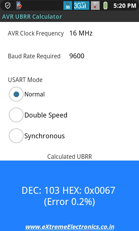 |
Fig. – AVR UBRR Calculator for Android |
Download
Initialization of USART
Before using the USART it must be initialized properly according to need. Having the knowledge of RS232 communication and Internal USART of AVR you can do that easily. We will create a function that will initialize the USART for us.
#include <avr/io.h>
#include <inttypes.h>

void USARTInit(uint16_t ubrr_value)
{

   //Set Baud rate
   UBRR= ubrr_value;

   /*Set Frame Format


   >> Asynchronous mode
   >> No Parity
   >> 1 StopBit
   >> char size 8

   */

   UCSRC=(1<<URSEL)|(3<<UCSZ0);


   //Enable The receiver and transmitter
   UCSRB=(1<<RXEN)|(1<<TXEN);


}
Now we have a function that initializes the USART with a given UBRR value.
That’s it for now friends. In next tutorial we will learn how to send and receive data over RS232 channel. Don’t forget to post your opinion or doubts or any suggestion I would be very happy to see them. So don’t wait post a comment now !
Other Parts of this Tutorial
- RS232 Communication – The Basics
- RS232 Communication – The Level Conversion
- Using the USART of AVR Microcontrollers.
- Using the USART of AVR Microcontrollers : Reading and Writing Data
- Visualize ADC data on PC Screen using USART – AVR Project
Finally, I’m starting to ‘get it’
Dear All,
Very nicely he has explain for beginners.
Regards,
Dnyaneshwar Sahane
@Dnyaneshwar Sahane
Thank you.
next will be I2C?? This will be greate…
Hi AM,
Ya I will surly come up with a I2C tutorials but before that I will complete USART tutorial by providing fuctions for reading and writing data.Then I will present my library for USART which is slightly complex (internally) but is more relibale and usefull. After that i will go for I2C
its very very interesting…
Pingback: Using the USART of AVR Microcontrollers : Reading and Writing Data | eXtreme Electronics
hi
I had been doing a project on polygraph with the help of program given by cornell university.but i dont knw which compiler they have used. v tried 2 use code vision but when v r xecuting prgm in proteus professional even if MATLAB is sending charector ‘s’,its not working.i would like 2 know which compiler they would have used.The prog is given below
CODE REMOVED TO SHORTEN THE COMMENT.
Dear friend, so nice tutorial!!!
regards:
Enrique.
Hi, I have ATmega8 and standart system clock is 1MHz. What I must change in code? and what baud rate need i set? from datasheet: Fosc=1MHz, Baud rate= 9600, UBRR= 6. Its correct? pls help.
Formula for calculation of UBRR is clearly given and explained above.
Also not EVERY baud rate possible. So Baud rate of 9600 on 1MHz CPU gives UBRR=5.51 and since we can use only integer for UBRR, using 6 as UBRR has huge error.
So go for other baud rates.
I recommend you to go with BAUD = 19200 which gives UBRR=2.25=2
OK and when I use external crystal? 7,3728 MHz UBRR=47 no errors, but i dont know what i must change in code and in avr studio??
Thanks for the handy info. It really helped clear some things up about programming for RS-232.
Hello Newman,
The two baud rate you calculated are correct. As you can see the above function we created takes UBRR value as argument, so simply pass the calculated values. Thats it !
Are you comfortable with c programming ? I mean do u understand what I said above.
See next tutorial’s code.
https://extremeelectronics.co.in/avr-tutorials/using-the-usart-of-avr-microcontrollers-reading-and-writing-data/
In the end I have given a complete demo program
Have a look at the main() function where we init USART by calling
USARTInit(51) //UBRR=51
Here 51 is UBRR value.
Simply change only this value to one you calculated and complile.
If you have any more doubts pls post in the forum (see side bar navigation), I will try by best to explain.
🙂 Have a nice day !
Hi Avinash,
Your website is a recent discovery for me. I am very impressed with your tutorials. They are very clear and easily understood. Thank you!
I am working with an ATmega32 processor and I am unsure exactly how the UART, baud rate, internal, and external clocks all work together. Can you advise me on this?
Some colleagues of mine are struggling with the Input Capture function of the same mcu as above. Do you have any information they can read to make this function clearer?
Cheers,
Paul
Hello Paul,
Thanks you liked my works.:)
I can’t get
“I am unsure exactly how the UART, baud rate, internal, and external clocks all work together. Can you advise me on this?”
please tell in some details so that I can help you.
Have A Nice Day 🙂
Paul when you use a internal rc oscilator 8MHz uart is no so reliable, when is good use external crystal with 7,3728MHz than is all correct. baud rate is speed sending data, i use 9600 baud rate…
Why is the internal RC oscillator not so reliable? For the external crystal what size of capacitors should I be using? I could calculate it but if you guys know already then maybe you could save me some time.
2x 22pF, look at datasheet atmega32
Hello,
I thank newman for helping Paul.
🙂
Good work.
As newman has said use 22pF capacitors.
For complete circuit see
https://extremeelectronics.co.in/hardwares/home-made-avr-devboard/
Internal RC is only for not time critical application. Because the frequency change with temperature. And USART is a time critical application. Crystal Oscillators are used in such application because they are very stable over temperature changes.
rs 232 and USART, are they a same method(protocol)?
sory if my question to sally..
Hello Apiz 🙂
RS232 is the “PROTOCOL” that means the standard “rule” for communication.
While USART is Universal Synchronous Asynchronous Receiver Transmmiter
It is a piece of hardware (commonly inside the MCU) that is used for RS232 Communication.
So now you know RS232 is a “PROTOCOL” while USART is a HARDWARE.
wow. now i understand how it actually works.
thanks
Hey very cool tutorial…is will this code also work with the UART on an ATMega168 MCU?
Hello Dave,
🙂
It will work with ATmega168 but you have to replace register names. See datasheet for equivalent name. Like UDR becomes UDR0 and UCSRA becomes UCSR0A.
Thats all
thank you!it was intresting!
Pingback: AVR ATMEGA8535 : USING USART [SERIAL COMM] « My English Blog
Hello Avinash!
Great tutorial series. Its a noble work to share knowledge.
I really enjoy the simplicity of your tutorials.
Keep Going!!
Best tutorials found online for newbies
thank you so much
now I dont have to guess the meaning of the code anymore 🙂
great job!
thanks again
Hey Avinash,
Just have a question in regard to the RS232 protocol. Can it be used to transfer entire blocks of data into the Atmega chips memory?
for example, if we want to store the data line “12345” in a special matrix in the memory, how should we go about it?
Thanks
Pingback: From extremeelectronics: AVR USART Tutorial | Solder In The Veins
for communication with microcontroller through hyper terminal, do v need to give any self & remote remote address
mitul tailor Says:
for communication with microcontroller through hyper terminal, do v need to give any self & remote remote address in the above given program
i dont know who are u Mr. Avinash,bt tell u have been amazing…so lucid explanation…just unbeleivable…I shal be gladly waitin to receive ur mail if u can kindly let me know about urself…
Hello abhinash,i want to communicate 2 ATMEGA16 through RF.if i connect 433mhz reciever and transmitter in RXD and TXD respectively in each ATMEGA16.Then if i’ll transmitt data frm one microcontroller then then,My question is -data will be receive by another ATMEGA16 or the same ATMEGA16?because both ATMEGA16 has 433mhz receiver..plz help me.
Hello Avinash!
These are Great and easily understood tutorial.Thank you very very much!!!!
In future tutorial can you Plese add some webcam or similer Cam interface to AVR family,I am waiting eagerly,Thanks again
Hello Avinash
Thanks a lot for your excellent articles. This is best place to start with for any AVR or infact any microcontroller beginner.
The way you explain the concepts is uncanny.
Dear Sir
I am vishal working on a project in which i have interface RF Module with ATMEGA 32L AVR Microcontroller for wireless communication.
I have already established the communication through wire using USART and adler32 protocol, But when i had connected rf module to the MC, I cannot communicate.
I had connected rf TX module to the TX PIN of AVR, and RF RX module to the RX pin of MC, Also i had made a common ground with powersupply, Still i cannot transmit the desired signal.
Should i connect some IC in between, or is there is another problem
Waiting for the solution
Regards
vishal
(vishalmeshram2007@rediffmailcom)
sir amazing tutorials i read from a lot of sites but nothing as clear as dis one……
sir my objective is to create a usart communication between two microcontroller.shld the information transmitted be first converted to binary form before transmitting through tx line or is the conversion internal. similarly if i want to see the data received should i convert the received data from binary to normal form
hello avinash
nice job avinash, this is the best avr beginers forum i found on internet.
i have a problem with with an usart implementation.
i tried implementing an usart code using internal RC oscillator at 4MHz using code vision.The hyperterminal displayed junk values(like “..[ “) instead of the chars “1? “2? or “3?,irrespective the value in UDR.
i even implemented the code given above, but the heyperterminal wasn’t accepting any input or displaying any output.
what could be the fault in this case?
is there a way i can rectify it?
there is also external crystal ocsilator on board but how to use it? as i am using codevision compiler it asks me oscilator frequncy
thanks
Pingback: RF Communication Between Microcontrollers – Part III | eXtreme Electronics
Thanks for the information! I personally really like your article. This is a great website. I will make sure that I stop back again!.
hey, am working on a project which involves communication between an simple arduino328p and arduino mega 1260. i wanted to knw since i am not connecting my UART to a CPU what register values(UBRR, UDR, UCSR) would i use?
hey, sorry..it was illy of me to ask that question.. i just saw carefully that you were not talking about the CPU in general but the AVR CPU… 😀
but thankx anyways for the wonderful tutorial
Hi Avinash,
Do we have any artical on I2C,SPI,modbus with the I2C,SPI libs for download. I am not able to find those on the site?
R u planning to write article on bitbanging with sample implementation in C?
@James
Such codes are currently unavailable.
Hi Avinash…..Thanx for your wonderful tutorial…I used the above code to send an integer value to my PC…But it shows just the ASCII character for that value….Can you please help…!!!
Convert Numbers (Integers) to string and them print the string thats it!
May be users should try to solve this kind of basic problems themselfs.
Hi Avinash,
I need ur guidance…I’m working on a project of controlling the speed and dir of Dc motor using avr mc..
-I’m using timer0 to generate pwm…
-external interrupts to select dir and different speeds..
-timer1 icp counts the encoder pulses,while timer1 ocra is set to read encoder count value after delay1.,this count value is then compared with some constant REGISTER value, to maintain set speed by changing pwm width!!!!
till here everything is fine,,,
Now i want to access and change that REGISTER in real time without the programmer… PLZ suggest me, how to go about it??? will USART help..
I made a simple spreadsheet that did the calcs for me so I could enter my clock freq and desired baud and it would tell me what the resultant baud rate and BSEL would be Works for BSCALE = 0 but could easily be improved. Email me simon at controlled-motion.com and i’ll send it to anyone who wants it 🙂
Thanks for the tutorial, wish I had found it before I slogged my way through figuring out how to use the serial port…
Pingback: Interfacing RFID Reader with AVR MCUs - AVR Tutorial | eXtreme Electronics
Pingback: More links « Sparktastic
I have learnt a great deal from Avinash’s tuts. I have two ATmega8 boards from Extreme electronics, really extreme. Learnt more than reading atmel datasheets etc.
Now the problem: I want to make two bots talk to each other or to a master control on wireless. I know wireless is “noisy”, hence require a proper “protocol”. This protocol has to be simple, not complex and byte eaters like the industrial Modbus etc. I will use the standard wireless modules available. Any help?
@Morawala
See
https://extremeelectronics.co.in/avr-tutorials/rf-communication-between-microcontrollers-%E2%80%93-part-iii/
Hey!
First of all, great tutorial! I am new to AVR and UART communications and your tutorial helped a lot.
I used your code and it seems to work OK, with one problem. I am able to send data to the PC, but not from the PC to the controller… The program seems to get stuck in the waiting loop :
while(!(UCSRA&(1<<RXC)) {}
I think this means that it is waiting for a character to arrive, but I keep on feeding it characters from the PC terminal, but nothing changes. So it seems I have a one way communication only.
What do you think the source of this problem might be? Thank you in advance!
Alex
@Alex
>> On PC you are using which terminal program?
>> What type of USB to Serial Convertor you are using?
Well, I’ve used several terminals: Realterm, one provided by the manufacturer of the board (Mikroelectronika) and a third one made by myself. And all with the same result.
The board I’m using comes equiped with a FT232RL chip, for which I didn’t install any special driver, I just let Windows 7 do the job. It all seemd OK, and Windows asigned it COM9.
Could it be a driver based problem? Or maybe a hardware one?
Hi Alex,
SOmetimes, we geeks look at simple problems in a complex manner. If you say that the terminal allows data reception, it means the terminal is OK. Have you checked the transmit wire? Is it showing continuity from end to end?
You know there are 3 wires,Rx, Tx & ground. All 3 have to be connected.
@ A M Morawala
Thanks man! Your comment made me turn my attention to the development board, and I realised the connection was somehow overrided by a pin setting for the RS232 chip (the board has both USB UART and RS232 ), so I turned that OFF and now my communication works both ways! 😀
Hi Alex. Glad to help:)
Nice tut
very useful conccept….
Brilliant series of microcontroller tutorials…!!! Hats off…!!
You must seriously write a book.. 🙂
Btw, I wanted to ask if i can use a normal bluetooth dongle instead of a dedicated bluetooth module. My bluetooth dongle has an ISSC chipset that supports HCI UART. So can I use HCI on ATMega16..?
sir
i have gone through your tutorials all were very nice and helpful. as i am new to this uart i have a atmega 128 kit (uniboard) given from my college. i need to transmit a data from hyper terminal to the microcontroller and need to display the value in the lcd provided in it. can you give me some guidance in it.
thanking you
dam
@Sam Joshua,
Please ask Uniboard dealer or your college for any help. Because they are the one who are getting paid from your Pocket.
We are not here to do the real magic for free.
Yes I may sound rude. But I cannot do a free tech support for Other Companies Board.
So please keep away such topics from here.
@Avinach
But you are paid NOT to be rude…!
@Ariyo
Who the hell pays me? !!!
I love your blog, great article, many thanks!
Hi
It is very usefull to us….
Hi dear Avinash
Where can I find some tutorial to better understand of bitwise operations you use in functions? For example, what does this mean? !(UCSRA & (1<<RXC)) or UCSRB=(1<<RXEN)|(1<<TXEN);
@Mahadi,
See this
https://extremeelectronics.co.in/avr-tutorials/programming-in-c-tips-for-embedded-development/
Also remembering one fact will help you
“We are writing programs in C”
So you must know C language (this is NOT a magical advice!)
If you knew C you already understood the above line !!!
Now for the not so rude answer.
UCSRB=(1<<RXEN)|(1<<TXEN)
RXEN and TXEN are constants, 7 and 6 respectively. So 1<<RXEN is 1 shifted left 7 places or 10000000 and 1<<TXEN is 1 shifted left 6 place or 01000000. Then the two values are bitwise ORed and the result 11000000 is placed in the register UCSRB.
I answered this because on first glance, the shifts didn't make sense to me because I did not know the value of RXEN or TXEN.
Thanks! 😀
Seems that UBRR is no longer directly handled via AVR Studio 5, immediate 16bit (2xregister) writing on UBRR doesn’t work, you should specify UBRRH,UBBRL independently.
Hello.How can I get/make a serial bootloader for an ATMEG16-16PU running at 16MHz? If the microcontroller has a bootloader (for 13.5Mhz) cold it be erase? Sorry if the subject is off topic.
Thanks
The frequency can only be changed by a crystal you need to solder on the two XTal pins. After doing that, you need to set the right “fuse bits” while flashing the MCU. Then the crystal is used, to alter the internal oscillator to the desired frequency.
Man I’m from mexico and my english is not the best but my congratuelations to you, this really helped me with my projects
Good Afternoon sir, thanks for your assistance that you have been rendering to many people, please sir i want a concise and comprehensive tutorial on PIC MICROCONTROLLERS because i am facing my final year project which is based on this type of MCU also i am appreciating the kind of simplicity of language you are using on this AVR MCu tutorial, Pls sir I need also the basics of LCD tutorial which is this part of your tutorials hoping my problems will be solved. Thanks Sir Avinash
If you’re looking for PIC samples go to mikroe.com but if you know “C” or “Pascal” the codes here are the same for PIC & AVR when you set the baud_rate and TX or RX a byte. the difference is in assembler code.
Pingback: RS232 Communication – The Level Conversion | eXtreme Electronics
Sir,
I am having a problem with my serial interfacing.I am using an usb-uart bridge(cp2102) to interface with atmega 16.
1)should i connect the ground of the bridge to ground of 7805 ?
2) when i connect the bridge to micronctroller’s rx and tx without powering the microcontroller on,i get my characters(entered in hyperterminal) echoed back,same result happens when i power on the atmega(i had programmed it to return character ‘b’).why is this happening ?
( 3<<ucsz0)
i can't ubderstand it
see this post
https://extremeelectronics.co.in/avr-tutorials/programming-in-c-tips-for-embedded-development/
Dear Sir
I want to control the speed of 230 V AC motor (submersible water Pump)through AVR 32A Mc. I have used PWM as well as also tried with 8 bit DAC (DAC0808) to Drive (BT12 A) TRIAC, but could not get the desired Output. Therefore need your help in this regard. What ckt should i use for controlling the speed of the AC motor,along with AVR 32A Mc.
please send me the solution on vishalmeshram2007@rediffmail.com OR
vishalgmeshram@gmail.com
Waiting eagerly for your reply
Regards
Vishal
look you need to sync the pwm with ac waves. So u need to sense the ac waves with an opto isolator. See this
https://extremeelectronics.co.in/avr-projects/avr-project-remote-controlled-fan-regulator/
Pingback: Atmega 32 programming for data transfer with clock synchronisation.
Sir can i send a message from atmega8l connected to a mobile or we need a pc to interface this to device?
HI, i just wanted to know if there are any specific library files i NEED to include as whatever program i am writing for USART communication, my AVRSTUDIO is returting errors like :
../usart.c:10: error: ‘UCSRB’ undeclared (first use in this function)
../usart.c:10: error: (Each undeclared identifier is reported only once
../usart.c:10: error: for each function it appears in.)
../usart.c:11: error: ‘UCSRC’ undeclared (first use in this function)
../usart.c:11: error: ‘URSEL’ undeclared (first use in this function)
../usart.c:12: error: ‘UBRRH’ undeclared (first use in this function)
../usart.c:13: error: ‘UBRRL’ undeclared (first use in this function)
../usart.c:16: error: ‘UCSRA’ undeclared (first use in this function)
../usart.c:17: error: ‘UDR’ undeclared (first use in this function)
I am using Atmega128 MCU
I have the same problem. I’ also using Atmega128. Is there anyone who can fix this?
the problem is in atmega128 there are two usart ports namely 0 and 1.
check out the datasheet of atmega128 .
If you are using usart0 then it’s ucsr0a,ubrr0l and similarly every other.
define
m128def.inc
first of all great tutorials.. all of them. learned a lot from them, thanks for that 🙂
i have question ,i am making a temperature data logger means i have used LM35 to measure the temperature and display it on lcd, till now its fine and i have also checked rs232 separetly its also working fine…thanks to your tuts.
Now i want to send these readings of temperature to PC using rs232 only..where i can display it on excel sheet with time HOW CAN I DO THIS?? ..PLZZ GUIDE ME..
google dharmanitech
i have that basic c prog ,but i still dont understand
3<<ucsz0
Pingback: Seeking FOSS serial port component which can handle 9 data bits | PHP Developer Resource
hello hw are U? fine
i do project using PIC 16f877 using mikroC and proteus for simulation and i want to programme it to parse data coming from GPS using usart only .how i can give a name for parsed data.example
$GPRMC,10,12,14,15,16.
i want the code which parse like below
$GPRMC,
latitude=10,
longitude=12,
time=14,
navigation=15,
dhsgds=16, so on and usart only write if first it get $ sign only unless doesnot write on usart.but the main thing is the numbers which come from GPS can vary but the order of the name which i give for the coming number is constant .
Pingback: GSM Module SIM300 Interface with AVR Amega32 | eXtreme Electronics
well done,layman can understand.Thank you,your sample codes are very useful.
Thanks Extremeelectronics.co.in
Can u tell what the statement 3<<UCSZ0 does precisely?
Hi,
When explaining the “UBRR: USART Baud Rate Register:”, the baud rate calculation has been shown.
It is said that Fosc is 16MHz and count for UBRR register is 51.
51 will come if 8MHz clock is used.
Below in the Android application calculation it shows as 103 which is the correct value.
Regards,
Sunil
Dear Sir , have you prepared the uart library for the functions that u have used in GSM module interfacing ?? If yes please provide it to me or give me a link .
thanks.
Gud evening sir, Its me,who I posted a doubt sir… It will be really helpful if you guide me to complete this…
two microcontroller is interfacing using uart where one is remote and another is like main board. remote will continously send some 8bytes values when no press in remote when we press button it send 8 bytes different values. main board also send continously some data like acknowledge but i am confusing that if i send same that values through terminal it nt responding..they using ATMEGA48
I love your tutorial!!!! thank you so much. It has taught me important things to get started with avr serial communication
sir plz give me full program for interfaccing gsm sim300 with at atmega16 in atmelstudio 6.1. plz sir. i m totaly new for interfeccing any interrupt in avr. plz help me
hello i want to use ad676 with atmega32 and send data to pc with usart please help me
how can i open batch file of computer using microcontroller….please help
Dear Sir
I am RAHUL, working on a project in which i have interface RF Module with ATMEGA 32L AVR Microcontroller for wireless communication.
I have already established the communication through wire using USART and adler32 protocol, But when i had connected rf module to the MC, I cannot communicate.
I had connected rf TX module to the TX PIN of AVR, and RF RX module to the RX pin of MC.
PLEASE GIVE ME ANY SOLUTION ASAP
Waiting for the solution
Regards
vishal
(vishalmeshram2007@rediffmailcom)
Hey
thanks a lot
I’ve a problem initializing UART. I’ve done all up but still PORTD (the port that is being shared with UART) is still acting like output pin. I mean I can change the value of PORT (PORTD.0 and PORTD.1) in my code (in codeVision)…I’m confused. How can it be possible?
how to read rfid tag 11 digit no. that is present on rfid using rfid reader…??
Hi Avinash,
<>
Is the above only for Atmega16?
Because I checked in the Atmega164P datasheet, this is not the case
The UCSRnC of Atmega164 does not have the URSEL BIT?
Good day,
Thank you for explaining re async operation.
I am interested in sync operation, using the the Z85c30 USART.
I find it difficult to understand the difference and application between –
DB25-15 Transmitter Signal element Timing DCE Source (DA)
17 Receiver Signal Element Timing DCE Source (DB)
24 Transmitter Signal Element Timing DTE Source (DD)
And interfacing it to the Z85C30
Can you direct me to any info or perhaps explain it to me classic RS232 (SYNC) operation for ‘beginners’ 🙂
Thank you very much