GPIO( General Purpose IO) is the most basic method of communication between MCU and external world. These are done with what is called a PORT. Ports are nothing but a set of bits physically connected to PINs of Microcontroller and available outside the chip. As we are working on PIC micros and they are 8 bits so the maximum size of a PORT is 8 bits. Some PORTs have fewer than 8 bits. You can turn each bit in a PORT on and off under program control. The bits which you set as 1 becomes HIGH and the physical PIN of Micro is at Vcc(supply voltage, usually 3.3v or 5v). And the PINs which you clear (=0) becomes low and physical level is 0v(GND).
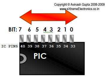 |
Fig.: PIC IO Port example, PORTB. |
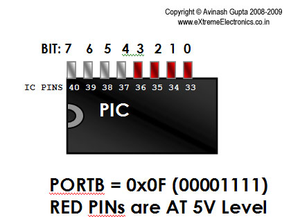 |
Fig.: PIC IO Port example, Using PORTB, Turning BITs on and off. |
You can test the operation of an IO port by using LEDs as shown below.
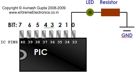 |
Fig.: When the bit is set to 0 the LED remains off. |
When you write a value 1 to corresponding bit the LED starts glowing.
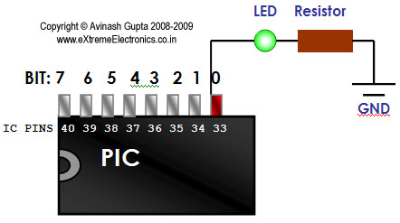 |
Fig.: When the bit is set to 1 the LED starts glowing. |
PORTs are Named like PORTA,PORTB,PORTC etc. The PIC we are using PIC4550 has the following PORTs
- PORTA(8bit wide)
- PORTB(8bit wide)
- PORTC(7bit wide)
- PORTD(8bit wide)
- PORTE(4bit wide)
Inputs using PORTs
You have seen how ports can be used to control the outside word. In that we have used the PORTs as Output. They can also be used to get input from outside. In input mode we can apply either logic 0 (GND) or 1 (Vcc = 5v) and we can read the status of PORT and get what input we have on ports. This can be used to interface switches and sensor with MCU. Any value below Vcc/2 is taken as low and any voltage above Vcc/2 is high.
A simple switch interface is shown below.
 |
Fig.: A Simple switch as Input to PIC Micro. |
The CPU can read the required port and take decisions accordingly.
Practical Stuff.
Having the knowledge about digital IO Ports on PIC micro we can begin some practical experimentations. So how can we actually access the ports in C? Well the answer follows.
Each PORT in PIC micro has 3 associated registers.
- TRIS: This is the data direction register – As I have told you that port can be used as both input and output purpose, the direction control (input or output) is done using this register. Simply make the bit as 1 when you want its as input or 0 for output.
Example:
TRISB=0xFF; //1111-1111 All InputsTRISB=0x00; //0000-0000 All OutputsTRISB=0x0F;//0000-1111 Bit 7,6,5,4, as Output and Bit 3,2,1,0 as InputNote: On power up all PORTs are Input.
To Remember this note that 1 looks like ‘i’ therefore Input, 0 looks line ‘o’ so Output
- LAT: (LATCH): This register is used to set output values. Anything you want output on related pins must be put on this.
Example
LATB=0xFF; //All PINs becomes highLATB=0x00; //All pins becomes LowLATB=0x03; //0000-0011 BIT 0 and 1 becomes high.
- PORT: This is used to get input from the PORTs. Reading its value gives the actual levels applied on the PINs. It must be noted that PORT is first configured as input using the TRIS register. Suppose you connected a switch as shown above on PORTB-0 then if you read PORTB it will be 0000-0000 if switch is pressed and 0000-0001 if switch is released.
Hi!
I am doing a project on leds using PIC12f675 .
I am using GPO,GPI,GP@ as outputs and GP$ as input to switch
Iwant to write aprogram so that when i press the switch once
all leds glow agin when i press switch
all three leds blink again when i press switch
only red led at GPO glows again press switch
only green led at gp1 glows ” ”
only blue led gP2 glows ” ”
only red blinks ” ”
only green blinks ” ”
only blue blinks ” ‘
back to all leds glow.
can you please help me. i would be very higly obliged.
Thanks in advance.
Naren
Naren309@gmail.com
Pingback: Using Analog to Digital Converter – PIC Microcontroller Tutorial | eXtreme Electronics
Pingback: Interfacing Ultrasonic Rangefinder with AVR MCUs | eXtreme Electronics
So far I know PORT is used to get input from PORTs as well as set outputs depending on TRIS register value. But in this tutorial it is shown that LAT is used to set outputs. I did not find this LAT in the datasheet of PIC16F628A. Could you please clarify this thing?
@shoeb,
This is for high performance PIC18F series MCU not midrange PIC16F series. So have a look a PIC18F4550’s data sheet not PIC16F628
The enhanced midrange PIC16F microcontrollers, such as PIC16F1829 has the LATx registers.
sir, i want to interface HCSR04, an ultrasonic sensor with pic18f4520. the sensor’s output is TTL. i am not able understand whether the pic actually receives the TTl output or not. i tried connecting it directly but it isnt working whereas the programming part is correct.
awaiting ur reply.
thankyou
this is help me a lot. till now i don’t know how to high or low our pic pins
thanks
ramesh jangra
Dear Avinash, I am new to Pic. why don’t you explain the tutorials with simple 12f675.16f628 instead of 18F4550? so as to understand even better. Thanks
Hi,
sir,iam very new to microcontroller,now iam using atmeha16 and avr stk500.
can you tell that code,if i am pressing sw0,the led lights are moving forward,press sw2 means led lights moving reverse.pls help me sir,
advance thanks
You wrote “the led lights are moving forward” if you are pression SW0. That is in present tense. It means it is already happening! So it implies that you already have the code?
So how can I help you?
Please be CLEAR while asking ? Don’t think people have any time or interest to read a badly written request !
sorry
Hi,
How do I make an LED turned on all the way until it is turned off by another LAT command. I cannot use delay because I need to execute another instructions while the LED is turned on. Thanks
@Paul,
Use a Timer with interrupt.
Hi Sir,
Thank You for your reply. Below is my source code.
Trans(0b00001000); Trans(0b00001001); if(address0f&&address1f)
{ LATC3=1;
}
else
{ LATC3=0;
}
I have the receive interrupt routine. But when the uP goes to receive interrupt routine the led turns off. So I cannot see the LED. Is there anyway to latch it?
Hi,
I am doing a simple led blinking program.If I use port b pin 0 as input how to make remaining bit of port b at a time as output.
Hi..I m making a project on ultrasonic based smart stick for the blind..can you help me out with how to interface pic 16f877 with ultrasonic sensor ..vibrators and buzzers..along with the program.
And the stick will vibrate whenever an object comes in front of the sensor..depending on the distance between sensor and object.. The intensity of vibrations and beep changes.
As it is written that using PORT, we can read the input. So, if i am giving decimals 1, 2, 3 and 4 (in form of hex, through a terminal) as outputs from my laptop to MAX232 through RS232, so that MAX232 can send these further to PIC16f877a in form of packets to make these as readable to the microcontroller, then, how should i check the data in the input pins in the microcontroller? Most probably, i can’t write directly that if(PORT_C7==1), do this, if(Port_C7==2), do this and like that. So, in what way should i programme to check inputs to perform different tasks on different datas i send through RS232. Should i use PORT_C7=getch() and then apply my if else directly comparing with 1,2,3,4 or something else i should do?
I am unable program my ‘PIC16F1938’ device using MPLAB ICD3, It shows an error : Target device ID mismatched.
Though i am able to do this using PICKIT 3.
I have checked pull up Resistor & Capacitors too, but getting same error using MPLAB ICD3.
Please help me with this.