Timers are common features of most microcontroller. In simplified terms a timer is just a register whose value keeps increasing (or decreasing) by a constant rate without the help of the CPU. The CPU can read or write this register any time. It reads it find out how much time has elapsed. The Timer register can have the following bit length
- 8 bit timers – These can count between between 0-255
- 16 bit timers – These can count between 0-65536
- 32 bit timers – These can count between 0-4294967296
A timer has a clock source, for example of the clock source of 10KHz is input to a timer then one increment will take 100uS (micro second). This clock source can be obtained from the CPU clock. The CPU clock of popular MCU ranges from 1 MHz to 20Mhz, this can be sometimes too fast. To help us out their is a thing called prescaler in the MCU. The job of prescaler is to divide the CPU clock to obtain a smaller frequency. The PIC Micro that we will use in this example has the following prescaler division factors available.
- 256
- 128
- 64
- 32
- 16
- 8
- 4
- 2
- 1 (Prescaler by-passed)
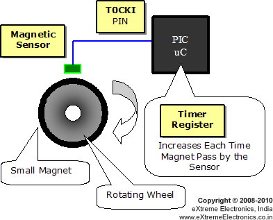
Timers are also called Counters this is because they can be used to count external events. The following example illustrate the fact.
 |
Counter Operation. |
The above setup can be used to measure the RPM (speed in revolution per minute) of the rotating wheel. A small magnet is attached in the edge of the wheel. Whenever this magnet is exactly below the Magnetic sensor its output becomes high. This output is connected to the T0CKI pin of the MCU. The T0CKI stands for Timer0 Clock Input Pin. So each time the magnet passes by the sensor the timer register inside the MCU is incremented. You can note one this that all this happens without the help of CPU. CPU can do other task and read the Timer register only when required.
Overflow
An overflow occurs when a timer register has already counted the maximum value it can count. At overflow the counter value become 0 again. For example when an 8 bit timer has the value 255 and receive another clock that will set it to 0 and generate an overflow. An overflow can trigger an interrupt and the ISR can handle it.
Using TIMER0 of PIC18F4520
PIC18F4520 has four different timers. The simplest is the TIMER0 so we will learn how to use it first. In this example the TIMER0 is configured as follows.
- 8 Bit Mode
- Clock Source from Prescaler
- Prescaler = FCPU/256 (Note: FCPU= Fosc/4)
- Over flow INT enabled
Our FCPU=20MHz/4 (We are running from 20MHz XTAL)
=5MHz
Time Period = 0.2uS
Prescaler Period = 0.2 x 256 = 51.2uS (Prescaler is set to divide frequency
by 256)
Overflow Period = 51.2 x 256 = 13107.2 uS (Each over flow takes 256 counts)
= 0.0131072 sec
So we need 1/0.0131072 Overflows to count for 1 sec
= 76.2939 Overflows
For that we maintain a counter to keep track of overflows.
When an over flow occurs the PIC jumps to ISR, where we increment the counter. And when counter becomes 76 we toggle RB1 pin. This pin is connected to LED. Therefore we have a LED which is ON for 1 sec and Off for 1sec.
Simple Program to Learn Operation of PIC TIMER0 in HI-TECH C and MPLAB
/*****************************************************************

A simple example to demonstrate the use of PIC Timers. In this

example the TIMER0 is configured as follows.

*8 Bit Mode
*Clock Source from Prescaler
*Prescaler = FCPU/256 (Note: FCPU= Fosc/4)
*Over flow INT enabled

As our FCPU=20MHz/4 (We are running from 20MHz XTAL)
=5MHz

Time Period = 0.2uS
Prescaller Period = 0.2 x 256 = 51.2uS
Overflow Period   = 51.2 x 256 = 13107.2 uS
                  = 0.0131072 sec

So we need 1/0.0131072 Over Flows to count for 1 sec
= 76.2939 Overflows

So we keep a counter to keep track of overflows.

When an over flow occurs the PIC jumps to ISR where we
increment counter. And when counter becomes 76 we toggle
RB1 pin. This pin is connected to LED. Therefore we
have a LED which is ON for 1 sec and Off for 1sec.


Target Chip: PIC18F4520
Target Compiler: HI-TECH C For PIC18 (http://www.htsoft.com/)
Project: MPLAP Project File

Author: Avinash Gupta
Copyright (c) 2008-2010
eXtreme Electronics, India
www.eXtremeElectronics.co.in

                     NOTICE
                  -------------
NO PART OF THIS WORK CAN BE COPIED, DISTRIBUTED OR PUBLISHED WITHOUT A

WRITTEN PERMISSION FROM EXTREME ELECTRONICS INDIA. THE LIBRARY, NOR ANY PART
OF IT CAN BE USED IN COMMERCIAL APPLICATIONS. IT IS INTENDED TO BE USED FOR
HOBBY, LEARNING AND EDUCATIONAL PURPOSE ONLY. IF YOU WANT TO USE THEM IN
COMMERCIAL APPLICATION PLEASE WRITE TO THE AUTHOR.

*****************************************************************/

#include <htc.h>


//Chip Settings
__CONFIG(1,0x0200);
__CONFIG(2,0X1E1F);
__CONFIG(3,0X8100);
__CONFIG(4,0X00C1);
__CONFIG(5,0XC00F);


unsigned char counter=0;//Overflow counter

void main()
{
   //Setup Timer0
   T0PS0=1; //Prescaler is divide by 256

   T0PS1=1;
   T0PS2=1;

   PSA=0;      //Timer Clock Source is from Prescaler

   T0CS=0;     //Prescaler gets clock from FCPU (5MHz)

   T08BIT=1;   //8 BIT MODE

   TMR0IE=1;   //Enable TIMER0 Interrupt
   PEIE=1;     //Enable Peripheral Interrupt

   GIE=1;      //Enable INTs globally

   TMR0ON=1;      //Now start the timer!

   //Set RB1 as output because we have LED on it

   TRISB&=0B11111101;

   while(1);   //Sit Idle Timer will do every thing!
}

//Main Interrupt Service Routine (ISR)
void interrupt ISR()
{
   //Check if it is TMR0 Overflow ISR

   if(TMR0IE && TMR0IF)
   {
      //TMR0 Overflow ISR
      counter++;  //Increment Over Flow Counter

      if(counter==76)
      {
         //Toggle RB1 (LED)

         if(RB1==0)
            RB1=1;
         else
            RB1=0;

         counter=0;  //Reset Counter

      }

      //Clear Flag
      TMR0IF=0;
   }
}
The program begins by Setting up TIMER0. The TIMER0 can be configured using a single register called T0CON which stands for TIMER0 control register. The details of each bit is given below.
| Name | TMR0ON | T08BIT | T0CS | T0SE | PSA | PS2 | PS1 | PS0 |
| Initial Value | 1 |
1 |
1 |
1 |
1 |
1 |
1 |
1 |
| BIT | 7 |
6 |
5 |
4 |
3 |
2 |
1 |
0 |
BIT7 – TMR0ON: Timer0 On, set this to 1 to start the timer.
BIT6 – T08BIT: =1 for 8 bit mode and =0 for 16 bit mode.
BIT5 – T0CS: Timer0 clock source. =1 for T0CLK pin input i.e. counter mode. Set to 0 for internal instruction clock.
BIT4 – T0SE: Used in counter mode only. Please see datasheet for details.
BIT3 – PSA: Prescaler Assignment. Set this to 0 to assign prescaler or 1 to by pass it.
BIT2 to BIT0 – PS2 to PS0: Prescaler Division factor select
| PS2 | PS1 | PS0 | |
| 0 | 0 | 0 | Divide by 2 |
| 0 | 0 | 1 | Divide by 4 |
| 0 | 1 | 0 | Divide by 8 |
| 0 | 1 | 1 | Divide by 16 |
| 1 | 0 | 0 | Divide by 32 |
| 1 | 0 | 1 | Divide by 64 |
| 1 | 1 | 0 | Divide by 128 |
| 1 | 1 | 1 | Divide by 256 |
So as per our requirement we have set the bits of T0CON register on program startup. This configures the TIMER0 as we require. Lets have a look at the code that initializes the TIMER0
//Setup Timer0
T0PS0=1; //Prescaler is divide by 256
T0PS1=1;
T0PS2=1;
PSA=0; //Timer Clock Source is from Prescaler
T0CS=0; //Prescaler gets clock from FCPU (5MHz)
T08BIT=1; //8 BIT MODE
TMR0IE=1; //Enable TIMER0 Interrupt
PEIE=1;   //Enable Peripheral Interrupt
GIE=1;    //Enable INTs globally
TMR0ON=1; //Now start the timer!
//Set RB1 as output because we have LED on it
TRISB&=0B11111101;
while(1); //Sit Idle Timer will do every thing!
As you can see in the above code, first we set up the bits of T0CON then we enable Timer Overflow interrupt, after that peripheral interrupt and finally enable interrupt globally. PEIE i.e. Peripheral Interrupt bit can enable or disable all peripheral interrupt. GIE or Global Interrupt bit is the master bit that can disable all interrupts.
Then when set PB1 i/o pins as output so that it can control a LED. The LED is connected to MCU by using series resistor to GND. Finally we enter an infinite loop that does nothing. As our timer is set up and running each times it overflows we increment counter by one. When counter becomes 76 we toggle the RB1 pin and reset the counter variable.
In HI-TECH C you can create an ISR (that is Interrupt service routine) by using the keyword interrupt. The ISR function can have any valid C function name. Its argument should be void and the return type should also be void. In our example we have named it "ISR".
void interrupt ISR()Whenever TIMER0 overflow the CPU stops it current operation and jumps to the ISR. This is called interrupt(or exception) condition. As soon as it enters the ISR we check if it is the TIMER0 overflow interrupt by checking the TMR0IF (Timer0 interrupt flag). We also check if the interrupt is enabled (by checking TMR0IE i.e. Timer0 interrupt enable bit). If both the conditions are met we execute the TIMER0 Overflow ISR Code.
Schematic for Testing TIMER0 of PIC18F4520
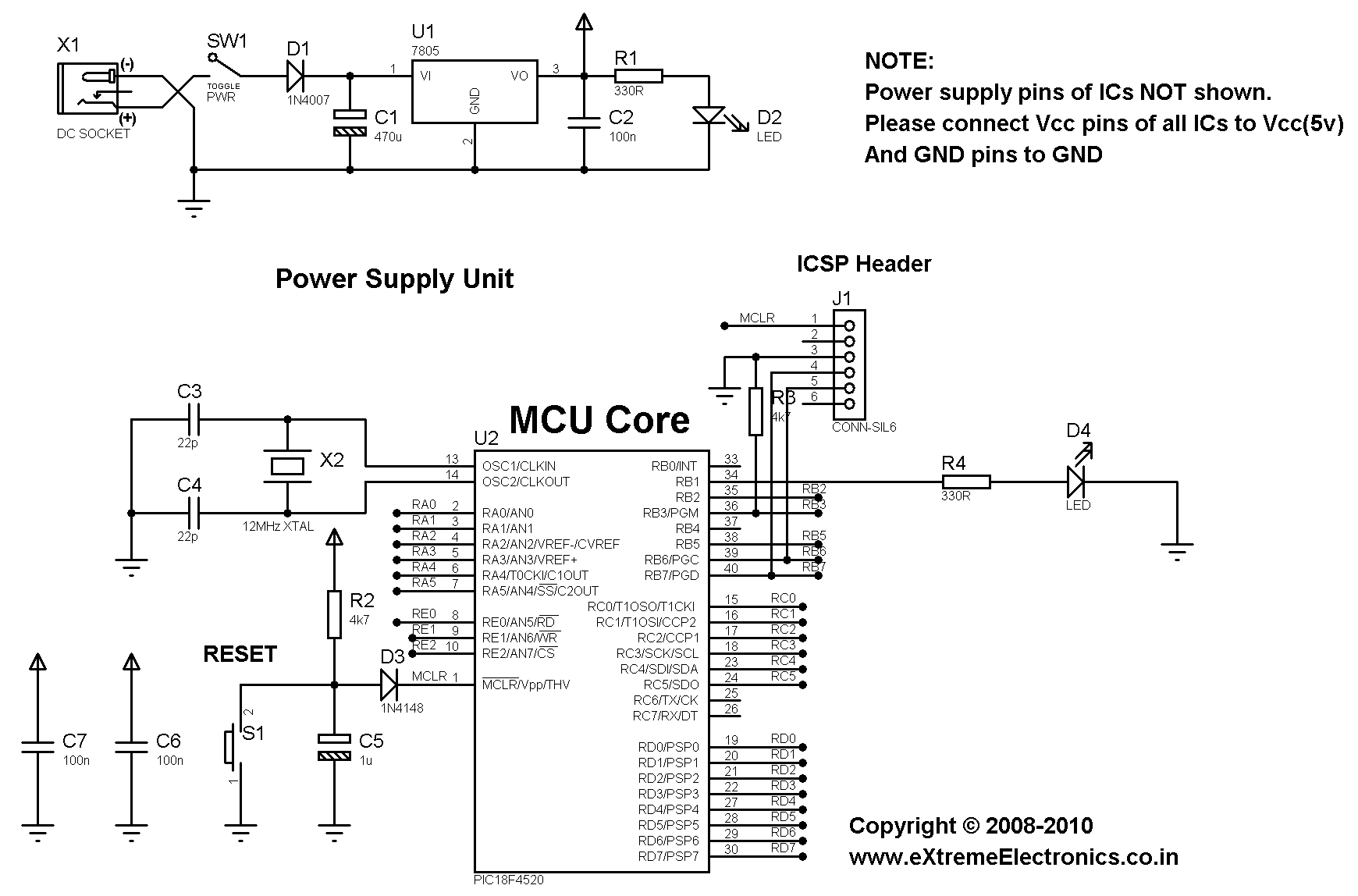 |
Schematic For Testing TIMER0 of PIC18 |
The circuit is described in this article.
Running Demo On 40 PIN PIC Development Board
The PIC development board from eXtreme Electronics has all core circuit required in most PIC projects. So we can use it to easily test the above demo program. All you need to do is to short jumper J5, this will connect the LED to RB1 that’s it!
PIC18 Sample Code Downloads
By
Avinash Gupta
May 13, 2010
he, i just looked at you’re tutorial, and it helped me thanks, i’m am a student computer technology in the Netherlands, what i really liked to know is, in you’re example you had time period 0,2 us, did you divide 1 by 5MHZ(1/5=0,2)
great totorial…
Donnovan
@Donnovan
Everyone knows Time Period = 1/Frequency !!! Nothing new here, I think even a 8th standard student know that !
@Avinash
i just like to be sure
Hi Avinash,
Good work… Keep it up.
I want you to update the below
16 bit timers – These can count between 0-65536
32 bit timers – These can count between 0-4294967296
to
16 bit timers – These can count between 0-65535
32 bit timers – These can count between 0-4294967295,
as the maximum value a 16-bit timer can count is 0xFFFF which is equal to 65535.
Similarly 0xFFFFFFFF = 4294967295.
Hi, I run your program on a PICDEM Plus 2 board but the LED stays constantly on. Any ideas why? Thnx.
Very good site guys, well done.
@George,
What MCU was installed on PICDEM 2 Plus?
Which programmer did you used ?
Did you also programmed the config area?
I use PIC18F4525 40pin. I use MPLAB with ICD2 and HITECH compiler. The XTAL is 16MHz but I changed the values accordingly.No I didn’t use the config part of your progra,. I assume that it affects the configuration bits that I control through MPLAB (HS and wachtdog off). thnx.
@George,
You have to write config area too. Try that and inform.
I added the config lines and it works fine. I’ll try to find on the net what those lines do. A kind suggestion would be to add comment to those lines. Thank you very much for your help.
Pingback: Introduction to PIC Interrupts and their Handling in C | eXtreme Electronics
This article is awesome and comprehensible. I can fully understand the concept of the article even I am just a beginner. Please carry on…I am looking forward to your subsequent articles (relevant to PIC)…best regards
Thank You Very mush for that special lecture. can I use this code on pic18f4550 by just changing the chip setting to my type of pic?
Pingback: PIC18F452 Timers/Counters Interrupts,...
Dear Mr.Gupta,
Hello.Thanks for your very interesting and usefull site.
I want to write a program using PIC18F452&XTAL=20MHZ in C to do the followings;
1.Simultaneously turn a timer on[timer1 or 2] to count for 1 sec. and
also count the number of High[transition from H to L] state of the
input signal.
2.Turn a timer on[timer1 or2] for 1 sec. and as soon as a input signal injected or entered to a PIC pin the timer[timer0 or…]immediately turned off and calculate the time of passed by that timer.
Would you please help and give me some example codes to write those programs?How can I modify that above program example to do the 2 above cases?
Thanks,
Pingback: Using Multiplexed 7 Segment Displays – PIC Microcontroller Tutorial | eXtreme Electronics
I used to be good at programming this puppies. But I have not touched them for three years now. I am having a big issue with the timer as a counter and as a timer. My question is I program in MPlAB IDE. I hated C in college. Is there a way you can post this execellent code in assembly. Thank you.
@Will,
Sorry but I don’t like programming in ASM.
Mr. Gupta:
The counter variable should be defined as type volatile.
This is a hint to the compiler that its value can change at any time, in this case due to the ISR routine.
Not doing so can lead to sections of code being optimized out since the compiler can think that section of code is unreachable.
-Arlen
@Arlen,
NOT all variable used in ISRs need to be volatile type.
Only those variable that are also referred (mainly read) in other parts of the code too, needs to be volatile.
Hello there, thank you for the useful information, I finally got what is the prescaler cause datasheet doesn’t refer to it. Well I work with PIC 18F4331 but this code does not work for me. They are different devices but the TMR0 is the same as I ve checked.
I made some changes , please have a look and advise since I am a beginner and I desperately need help!
I have a 10MHz oscillator, and set 1:4 prescaler.So according to the above
FCPU=10/4=2.5 MHz
time period=0.4 us
prescaler period=1.6 us
overflow period=6.4 us
thus we need 156250 overflows to reset the timer, right? I ve tried different prescalings but nothing changed..
I m not sure how we decide which prescaling to choose!! :64 or :256
The only changes I ‘ve made to the code are ;
T0PS0=1; //Prescaler is divide by 4
T0PS1=0;
T0PS2=0;
T016BIT=1; //8 BIT MODE
TRISC=0b11111111;
if(counter==156250)
{
//Toggle RC3 (LED)
if(RC3==0)
RC3=1;
else
RC3=0;
counter=0; //Reset Counter
}
Xcuse me I meant the counter has to reach 2441 to overflow, my mistake, but it doesn’t work again!
@aredhel_vlsi
One thing you should make sure is the CONFIG bytes are written correctly.
You should first consult the datasheet that describes the CONFIG bytes.
Other one is the part that deals with the oscillator configuration, since you are a beginner your should read this section throughly and find out how to configure the oscillator then you need to set the CONFIG bytes accordingly. Only then you may proceed to other tutorials.
I are done all this work but it applies to PIC18F4520 only.
The TIMER part may then be easily ported.
ok, can I ask, the configuration bits are standard for the device an Oscillator I use, right? I ve set them and my program works correctly for another code with simple delays. Its just it doesn’t work with the interrupt.
Are my calculations right ? because the difference is not big to 18f4331 acoording to the datasheet.
How will I choose the proper prescaler?
Thank you
Friend your OVERFLOW PERIOD is wrong in that it is a product of PRESCALER PERIOD AND COUNT. i.e 1.6 x 256(8bit count) = 409.6uS.
thus, we have
2441 overflows in 1second
thank alots..b4 this..im stuck at the “timer”
now u give me clear about this timer..
Your tutorial was quite interesting and helpful,but I have a question about the timer.Can u pls tell me one practical use of timer with example??Because I am not sure if have fully understood the concept.Thank you 🙂
Okay if any one could please help with my project,
my limits is that i use PIC C compiler and Proteus design software for the project.
Farmers’ Tank
-Tank need to be filled up everyday at specific time adjustable by farmer
-Tank level % must be displayed on the 1st line of an lcd
-time to fill tank must be displayed on second line time to be logged for up to 40 days downloadable via rs232 port and clearing data after download
-Use LEDs to indicate pump running , tank full, tank empty.
-include a relay and motor to represent pump
–
Pingback: Timer0 interrupts on PIC18F4620
Pingback: pic timers and prescal of timers in it
Follow the instructions properly !
I want to use PIC 18f452 for all the things in your tutorials that is ADC, Sensor interface, LCD expansion board, timers, serial communication etc
please tell me that what changes i have to make for running these codes (that are for PIC 18f4520) to make them run for PIC 18f452???
Hi !
Thanks for this tutorial. It was VERY helpfull for me to understand how these timer work. I didn’t find another tutorial as clear as yours !
I could write my own interrupt routine and it works perfectly.
If i understand it right, you can’t set precise timings, as it is always a combination of clock fequency and prescaler value, so approximative timer value?
It is not possible to flag the interrupt for a precise internal counter value.
Thanks again,
@Patrick,
Yes it is possible. But this is only the simplest explanation.
is this “void interrupt ISR()” only specific to hitech c. I am using micro c,
can I use as follows?
if(counter==76)
myISR();
what is the advantages/disadvantages of these two methods?
Please let me know one more thing….
what does the following code mean? what does the function __CONFIG(a,b); actually do?
__CONFIG(1,0×0200);
__CONFIG(2,0X1E1F);
__CONFIG(3,0X8100);
__CONFIG(4,0X00C1);
__CONFIG(5,0XC00F);
Your work is appreciated …
Hello and thank you from France!
Thanks to you, I understand how to use timers and implement in my project.
I imagined that the task was daunting, but no.
Thank you again and good luck for your future projects. 🙂
@Tom,
Thanks a lot !
thanx for valuable information………………………….
@Anand Raut, welcome
Hello sir,
How to use TIMER1 in PIC18f4520 for external frequency counting up to 5MHz
@Shweta,
There can be two different methods by which frequency can be measured.
In first method we can count the number of peaks and wait for one second. The number of peeks counted in one second will be the frequency.
The drawback is that this is slow(because we get data only after one whole second) and only gives us average frequency.
But is good if the user want to display this data to humans.
But if the data is to be used to control other parts of system. Then it may require that frequency can be calculated much faster. Like in case of a vehical fuel injection system
In this case we need to timers. One is used as a counter for peaks and other keep tracks of time and notify us when 1 second has elapsed.
On second method we measure the time between peaks.
hello,
In the above program why peripheral interrupts are enabled??
PEIE=1; //Enable Peripheral Interrupt
@Sujin, Because TIMER is a peripheral!
Hi i was adopting the same code for pic18f45k50 but i am unable to execute pls share the exact files in mplab or microc
“pls share the exact files”
which exact files?
I thought pic18 microcontrollers has 16 Bit Timer 0, why not use the option so that you have less interruptions in your programs.