Thanks for selecting PIC development board from eXtreme Electronics. Now lets get familiar with this powerful and easy to use system.
Introduction
This board will help you build and test any project with PIC microcontroller quickly and easily. It can be used to work with any 40 PIN PIC micros. The board provides the basic environment for the PIC to run. The great advantage of the design is replaceable prototyping area. All ports and power supply is available on 40 PIN female connecter. You can easily attach a normal veroboard with help of 40 PIN male headers. Now all PORTs of MCU is available on the veroboard where you can design the rest of your project. In this way you can create many different project with same development board, you just need a blank veroboard. By using this technique the "rest" of your project and the development board are paired firmly, both electrically and physically, yet flexibly separable!
Features
- Incircuit Serially Programmable with eXtreme Burner – PIC.
- PIC
18F4550 Included
- USB 2.0 Support
- Running @ 48 MHz (12MIPS) with 20 MHz crystal. (Using on chip PLL)
- Inbuilt 5V regulator with reverse voltage protection
- Power Switch (on/off)
- Power LED
- Reset Button
- RS232 Interface with DB9 male connector.
- 2 x Extra 5v Out
- All ports on linear 40 pin female connector.
- Replaceable prototyping area
- 1 user programmable LED
- 1 user programmable Button.
- Add on Board Support (Many Add-ons Coming Soon…)
Board Overview
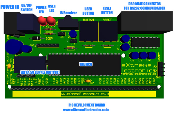 |
Fig. Overview of PIC Development
Board. |
- POWER IN – This is a standard DC adaptor socket where you can connect a 12V DC adaptor to power the whole system.
- ON/OFF SWITCH – To Turn On and off the board use this switch.
- POWER LED – Indicates the status of power in system
- USER LED – This LED is connected to RB1 through jumper J5. This LED is used as a user programmable LED. When you no longer need this LED in your project you can easily disconnect is by removing the jumper J5.
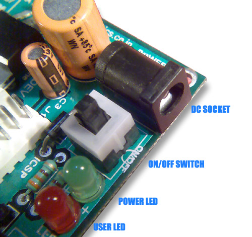 |
Fig. DC Socket, On/Off Switch
and LEDs |
- IR Receiver – A 38KHz Modulated Infrared received module for IR data communication (like IR remote). The output of the module is connected to RB0/INT0 of the MCU. When an IR light modulated at 38KHz falls on this sensor the output becomes LOW(0V). When no IR light is available the output is HIGH(5v).
- USER BUTTON – This button can be programmed for input. It is connected to RB4
- RESET BUTTON – Resets the MCU.
- SERIAL PORT – Used for communication with PC and other RS232 devices.
- EXTRA 5V OUT – Provides a regulated 5v output. It can be used to power external hardware Their are two 5v supply onboard.
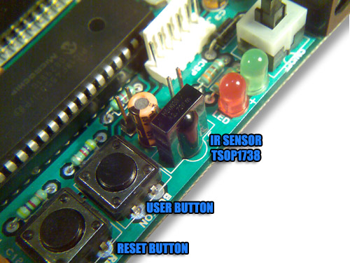 |
Fig. IR Sensor,User Button
& Reset Button |
 |
Fig. Serial Port |
- ICSP PORT – This is a Six PIN male connector used to upload programs to the microcontroller.
- EXPANSION PORT – Now this is the most special feature of our PIC development board. All the PORT PINs of MCU and extra Power Supply is available as single 40 PIN Female Connecter. Here addon boards (like User Interface Board, Motor Control Boards or Custom boards can be connected. For more information on this technique please see expansion support.
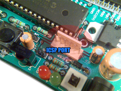 |
Fig. ICSP for Program Downloading |
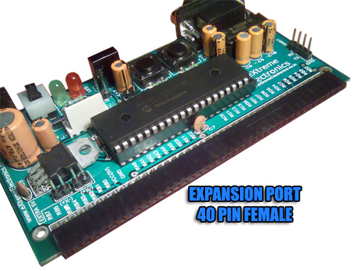 |
Fig. Expansion Port for Addon
Board Connection |
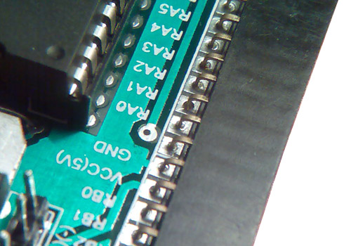 |
Fig. Expansion Port for Addon
Board Connection |
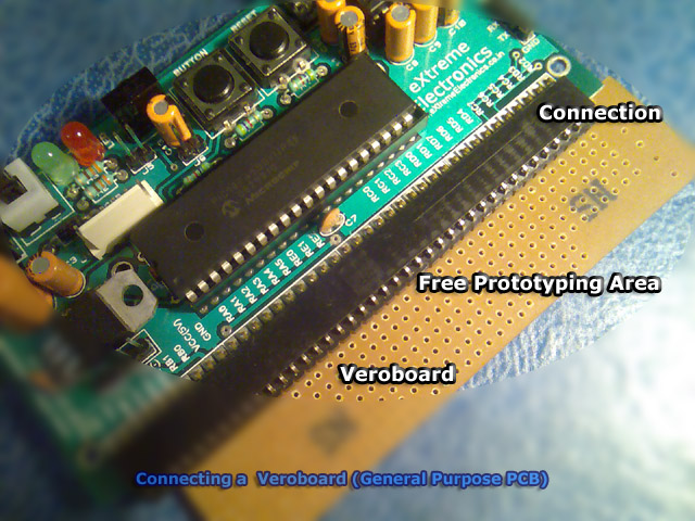 |
Fig. A Vero Board connected
to expansion port. |
Return to Help Index.
i want to know about microcontroller programming and burn read a programme or copy the programme to other
HI I M RAMAKISHNAN WORKING AS AASST PROFESSOR IN VEL TECH ENGG COLL WE R DOING PIC MICROCONROLLER LAB WE NEED ONE BURNER KIT . WE R USING PIC 18F258 MCU.IF POSSIBLE FOR SAMPLE ONE OR ANY REDUCTION PLS SEND MAIL TO ME.
@Mr. Ramakrishnan
Sorry sir.
Hey, is there any step by step guide to build a 40 pins PIC development board like the AVR development board ?
@Vick
NOT at all! Who will pay for the bread(or beer) of our engineers?
I have required a pic 12f675 developer and programming board, is there any kit with u which can support pic 12f
serise.
Do you have bare PCB(generic) for PIC 40 pin. It must have routes for LCD (doesn’t matter the port); module for power supply (with +5 V and +12 V, optional), and pads for accessing all the ports (optional to have double pads). We are looking forward for a bulk order, so kindly reply to my mail
hi.. m asd to develop a lcd interface with pic 18… cn u tel how to do it… like wat all i shd buy frm u nd after which u shd also help me build t… if u cn mail me.. i wil purchase immediately
@Saranya,
Please see this
https://extremeelectronics.co.in/microchip-pic-tutorials/making-the-lcd-expansion-board-for-pic18f4520/
Can i get a link to the schematics ?
Hello Avinash,
I am interested in buying two nos of PIC development boards. As I already have a PIC-KIT-3 programmer, please let me know if these Development Boards are compatible with the said programmer.
@Deepak Nair
Yes compatible.