This article describe the hardware setup required for interfacing HD44780 based alphanumeric LCD modules with a PIC16F877A microcontroller. The software part consisting of the LCD library for PIC, its setup and use with MPLAB X IDE and XC8 compiler are described in a separate article.
A common controller chip used in many alphanumeric LCD module is the HD44780. The purpose of the controller is to generate pixel patterns and drive individual pixels of the LCD to show characters and symbols. In this method the main microcontroller running your application code does NOT need to generate the pixel patterns, it just need to tell the controller chip which character or symbol to show the rest is done by the controller, i.e. the HD44780.
The same controller chip is used in many differently sized alphanumeric LCDs. Thus the connection schematic and driving code is same.
Pin Details of LCD Module
All HD44780 based LCD modules have 16 pin connecters. The detail about these pins is given below.
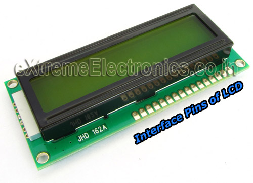 |
Interface pins of LCD Module |
| Pin Number | Pin Name |
Pin Type | Connected with PIC16F877A’s pin |
| 1 | VSS | Power Supply | – |
| 2 | VCC | Power Supply | – |
| 3 | VEE | Contrast Adjust | – |
| 4 | RS | Control Line | RD4 |
| 5 | R/W | Control Line | RD5 |
| 6 | E | Control Line | RD6 |
| 7 | DB0 | Data Line | – |
| 8 | DB1 | Data Line | – |
| 9 | DB2 | Data Line | – |
| 10 | DB3 | Data Line | – |
| 11 | DB4 | Data Line | RD0 |
| 12 | DB5 | Data Line | RD1 |
| 13 | DB6 | Data Line | RD2 |
| 14 | DB7 | Data Line | RD3 |
| 15 | LED+ | Backlight Power | – |
| 16 | LED- | Backlight Power | – |
Common modules works with 5v supply. Pin 1 is connected to GND and pin 2 is connected to +5v supply. The pin 3 is the contrast adjust pin and proper wiring of this pin is very important to get anything visible on the screen. Even if you have done everything perfectly, but an improper wiring of this line can lead to a complete blank display !
A 10K preset is used as a voltage divider to get any voltage between 0v and 5v. This voltage is feed to the VEE pin. So after everything is ready and you have programmed your PIC Micro to show something on the LCD, you have to adjust this preset before you can see anything on the LCD.
Then their are three control line, namely the RS, R/W, E. these are connected to microcontrollers general purpose input output line.
After that comes the data lines DB0 to DB7 (8 bit wide). These are also connected to microcontrollers general purpose input output line. The HD44780 controller also has a 4 bit data transfer mode. This mode is very useful as it uses only 4 bit lines to transfer the whole 8 bit data. The data is transferred in two transfers each of 4 bit. Thus this technique requires only four i/o line of microcontroller in place of eight. This smart saving of i/o lines is very useful as you are free to use the saved i/o lines for other purpose in your design.
In four bit transfer mode, data bits DB0-DB3 are left unconnected only DB4 to DB7 are connected with microcontroller.
Finally comes the backlight power lines. As you may be knowing the backlight helps viewing the contents of the LCD module in dark situations. Making the backlight lit is simple, as it is just a set of LEDs. You need to supply +5v and a GND connection to make it glow. But as with any LED it is suggested to use a current limiting resistor in series with the backlight. The resistor we prefer is a 100ohm resistor (a 1/4th watt resistor is enough but you may use 1/2 watt also).
Complete schematic of the LCD subsystem is shown below.
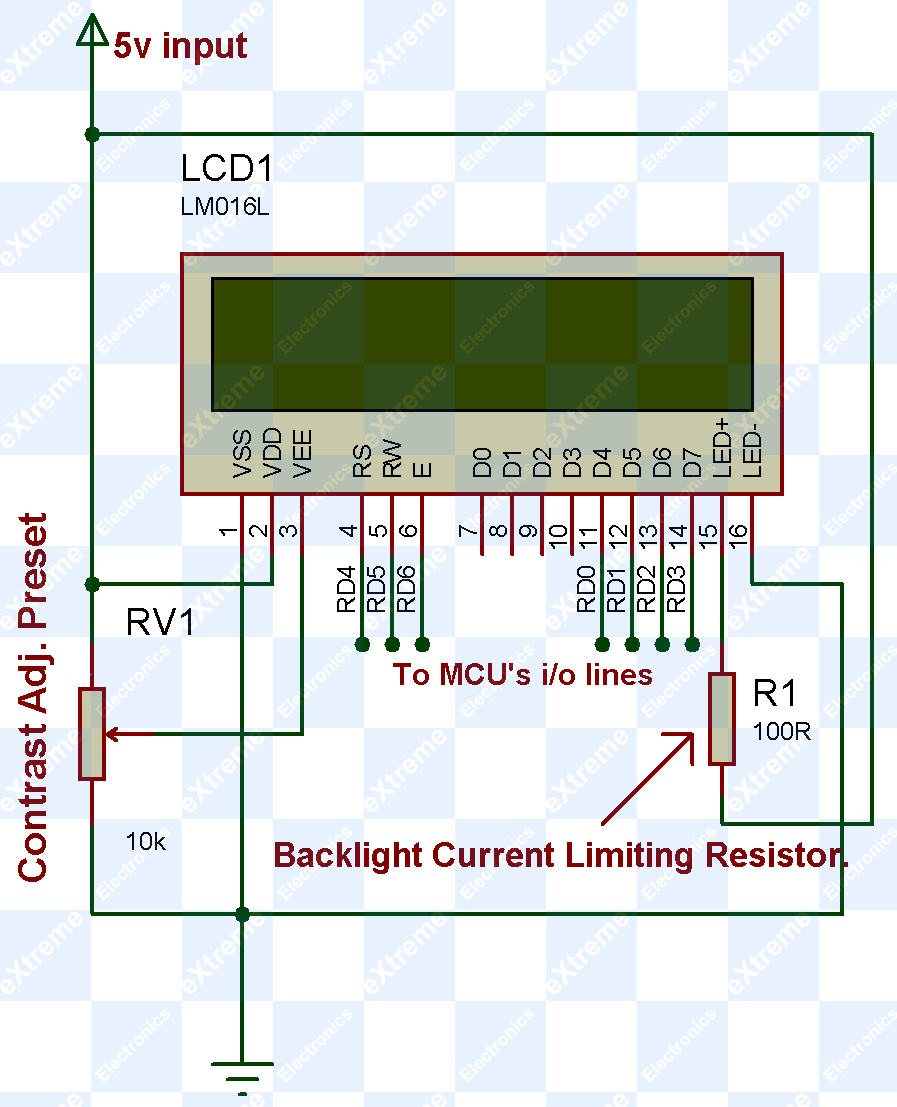 |
LCD Module Subsystem |
16×2 LCD Board
The 16×2 LCD Board makes it easy to interface a 16×2 LCD module with low cost microcontroller development board which do not have built in support for lcd modules. This board has the following
- 16×2 lcd module (you can choose either a green or a blue backlight lcd)
- The contrast adjust resistor.
- Backlight current limiting resister.
so you can see that it has all the things required by the lcd subsystem in a nice pcb.
In addition to the above, it also has the ability to turn on or off the lcd backlight and also control its brightness using pwm technique.
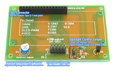 |
LCD Board Description |
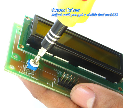 |
Adjusting Contrast |
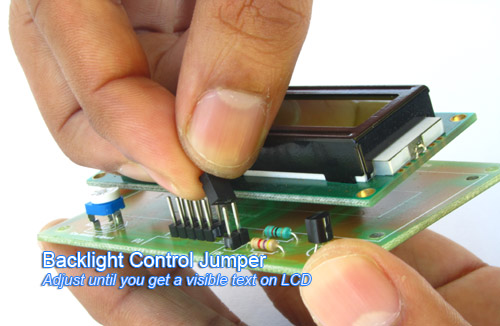 |
Backlight Control Jumper |
Connecting with PIC16F877A Development Board
The PIC16F877A development board as the PIC16F877A microcontroller chip and its supporting basic circuitry all in a nice high quality PCB. The development board comes fully assembled and tested, thus makes it ideal for doing experiments for learning by beginners.
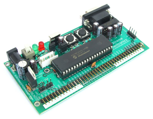 |
40 PIN PIC Development Board |
In the bottom portion of the pic development board you can see a row of male headers. Most of these pins are the microcontrollers general purpose input/output lines and the rest are 5v and GND supply lines. Using these pins you can connect external peripherals (like the LCD board or something else) to do your experiment. The pins are clearly labeled on the PCB surface.
Since other peripheral boards also have male headers for interconnection, you need a female to female burg wires like these to make connections.
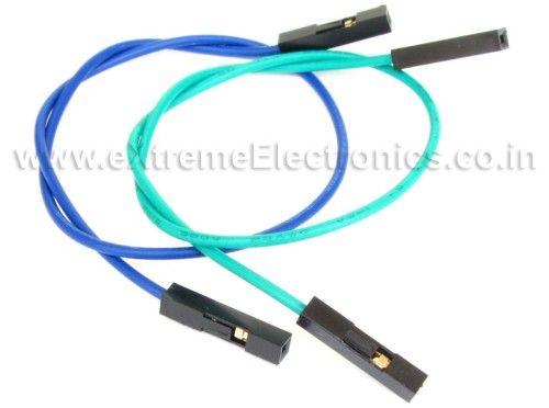 |
Burg Wires |
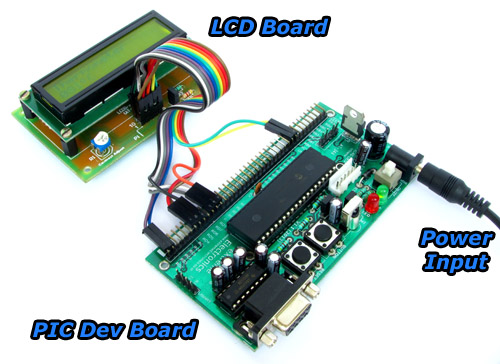 |
LCD Board Connection |
Connect LCD Board with the development board using the above mentioned burg wires according to the table given below.
| LCD Board | 40 PIN PIC Dev Board |
| 1 R/W | RD5 |
| 2 RS | RD4 |
| 3 LED PWM | Not Connected |
| 4 VCC | 5v |
| 5 GND | GND |
| 6 DB7 | RD3 |
| 7 DB6 | RD2 |
| 8 DB5 | RD1 |
| 9 DB4 | RD0 |
| 10 E | RD6 |
5v and GND connection points are labeled in the development board as Extra 5v OUT. Please refer to the image below for their positions. 5v and GND are also available in the 40 pin row of male headers. In the image below Yellow wire is 5v and Green wire is GND.
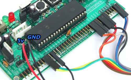 |
Close up of Connection. |
Schematic of the whole setup
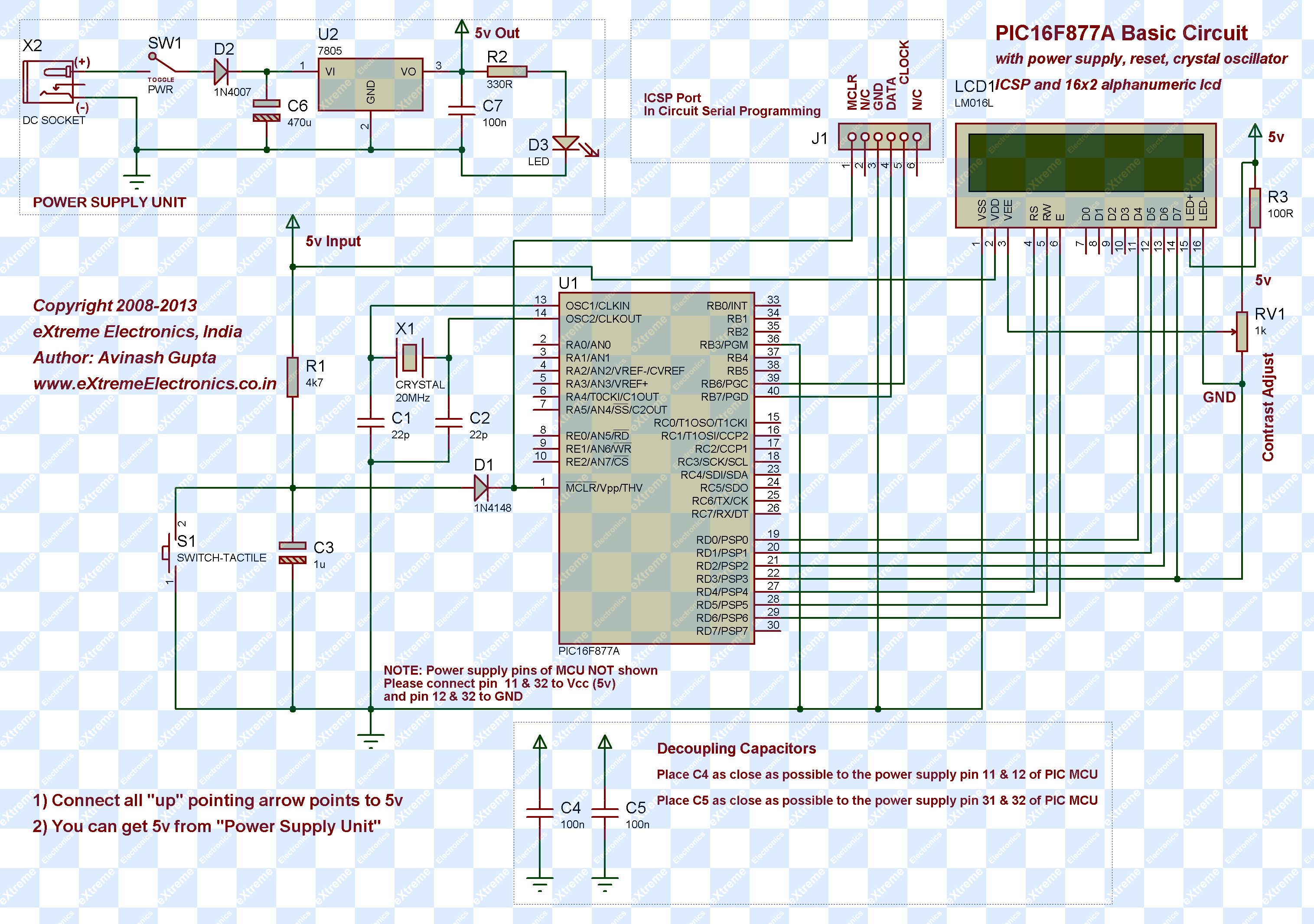 |
PIC16F877A Interfaced with LCD Module Schematic (Click to Enlarge …) |
Next Part
- LCD Library for PIC – Setup on MPLAB X IDE This article describes the setup and use of the C library for hd44780 based alphanumeric lcd modules. Here we describe how to setup a MPLAB X project with support for lcd related functions. The library is designed for compilation and use with Microchip’s XC8 C Compiler.
By Avinash Gupta
www.avinashgupta.com
Mr. Avinash,
Thank You so much, a new article after long long time, We want to see this site alive and vibrant.
Expecting also PIC KIT 2 or 3 from you
Regards,
Uttam
Ok Dada you are most welcome.
Pingback: Setup and Use of LCD Library for PIC |eXtreme Electronics
A big thank you
I am new to writing programs only ever flashed chips
Getting a bit old now but something I want to learn.
Regards
Dave
Ok Dave you are most welcome.
Hey, THANKS A BUNCH for this Great article and your effort!! Done this without any problem.…
I am recently working on <> project. Everything goes well, but facing a problem which is getting a continuous signal from PIR SENSOR. May you please help me just telling me How to adjust the sensor to get SIGNAL only when Motion is detected!!!
Help me bro,PLS.
hello,thank u so much sir,i really like this artical .but,having some problum to understand about using components……please help me.about this artical for more understanding about it. i will be thankful to u for this,
What happens if we left open the led+(15) n led-(16) as we use to do in simulation??
@Shivaraja sajjan Why to you wanna increase trouble in your life?
If the display is transmissive time, you won’t see anything !
MY REQUEST TO EVERY ONE DO EXPERIMENTS EXACTLY AS TOLD !
DON’T GO FOR SILLY MODIFICATION AS DONE BY ABOVE GUY Shivaraja sajjan!
Hello Sir, Please am not good at writing programs and i have a project on Motor speed Monitor and control systems using a GSM modem. I dont know how to write a program for the PIC 16F877A to communicate with the GSM Modem, LCD, Optical encoder . Really thankful if u can help me here…
i am happy with u ….next to this posting pic16f877a+microc language rather than mplab is more applicable
Hi
Has anyone got Lay files for the PIC16F877A Interface and LCD module or even split into 2 parts will help.
Regards
I sir I am not a program writer could you help me for pic 877 .purpose for using lcd meter to read input &outpui voltage.
can u please send the code???????
Thank you so much….Its really useful