Tag Archives: atmega32

Simple Single Motor Control using AVR ATmega16

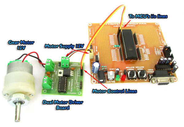
Microcontrollers are good when it comes to brain, but to do anything in real world they need muscles too ! Their muscles are electromechanical actuators like motors. Their are several types of motor available to do various type of motion. The simplest of them are DC motors. They can generate rotary motion and when wheels are attached to their shaft they can be used to move a body. Applications include motion of a robot on flat surface like a floor. Normally a DC motors runs at a high RPM, so to slow it down a gear head is attached in front of it. This makes RPM come down to values such as 50 RPM to 500 RPM. This also increase the torque online casino no deposit generated by the motor. The image below shows a 12v DC Gear Motor. The front black portion contains the gear assembly. Fig. A DC Gear Motor In this tutorial we will learn the basics about these motors and how to control them using a microcontroller. DC Motor Rotates in one direction when you apply power to its terminals. When you reverse the polarity of the supply it will rotate in opposite direction. Since a DC Motor requires current in the range of 400ma to 1000ma we cannot supply them directly from the MCUs I/O […]

Comparing Low Cost AVR Dev Boards

Over the years I have seen people just open up the mouth without thinking. This is more common in the young age group like those of students. Often this also miss leads others. Recently we posted and ad on Facebook for our low cost development board which was priced at Rs. 299. Some guy without thinking a minute, compared it with a even lower cost product from some other vendor. What my point is that those two products are NOT similar ! Their are HUGE differences ! So I thought I should make out those differences stand out. Power Supply Our Board Probots’ Board Has built in 12V to 5V regulator circuit built using 7805 IC. No regulator. Advantage   You can power up the board using an adapter of any voltage output between 9v to 18v Using higher voltage adapter has the advantage that power from it can be used to driver higher voltage devices like relays or motors. You can power up using a 5v adapter only! If you need 12v supply to power relays or motors you need a separate adapter or battery.   Power Switch Our Board Probots’ Board Has an on/off switch No on/off switch Advantage   Easy power control. Frustration on long run.   Prototyping Area Our Board Probots’ Board Has large prototyping area […]

Interfacing TCS3200 Colour Sensor with AVR ATmega32

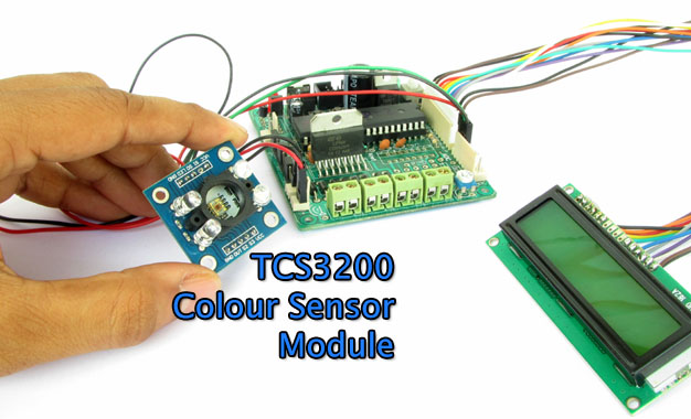
Detecting colour of an object can be an interesting and useful electronic application. It can be realized using a colour sensor like TCS3200 and a general purpose microcontroller like AVR ATmega32. TCS3200 Colour Light to Frequency Converter Chip Fig. TCS3200 Chip .   TCS3200 chip is designed to detect the colour of light incident on it. It has an array of photodiode (a matrix of 8×8, so a total 64 sensors). These photodiodes are covered with three type of filters. Sixteen sensor have RED filter over them thus can measure only the component of red in the incident light. Like wise other sixteen have GREEN filter and sixteen have BLUE filter. As you should know that any visible colour can be broken into three primary colours. So these three type of filtered sensors helps measure the weightage of each of primary colours in incident light. The rest 16 sensors have clear filter. TCS3200 converts the intensity of incident radiation into frequency. The output waveform is a 50% duty cycle square wave. You can use the timer of a MCU to measure period of pulse and thus get the frequency. The output of TCS3200 is available in single line. So you would ask how we get the intensity of RED,GREEN, BLUE and CLEAR channels? Well it has two inputs S2 and […]

SMS Based Voting System – AVR GSM Project

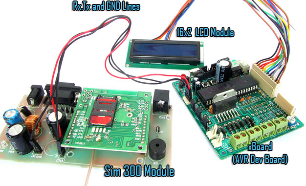
If you want a live demo of this, please register from the link given below. (Only in Pune) REGISTER NOW! This project can also be implemented using a PIC18F4520 microcontroller. Hi friends ! Here I am showing a microcontroller based project called the "GSM Based Voting System". Using this system you can ask your users to vote for any of the four options. Four available options are identified by a letters ‘A’, ‘B’, ‘C’ and ‘D’. User can vote for any option by sending a text message to the mobile number. For example if you want to create a poll like this. Which is your favorite phone brand? A: Nokia B: Apple C: Samsung D: L.G. So your user can vote for any of the four brands by sending a message like this VOTE x where x is the choice he/she wish to vote for. For example if they want to vote for Nokia, then they should send a message like this : VOTE A The number of vote received for each option is shown in real time on the LCD Module. The votes are stored in the internal EEPROM of the AVR so they are not lost on power failures. That means even if you switch off the device and switch it on after few days (or few years!) […]

Sending and Receiving SMS using SIM300 GSM Module

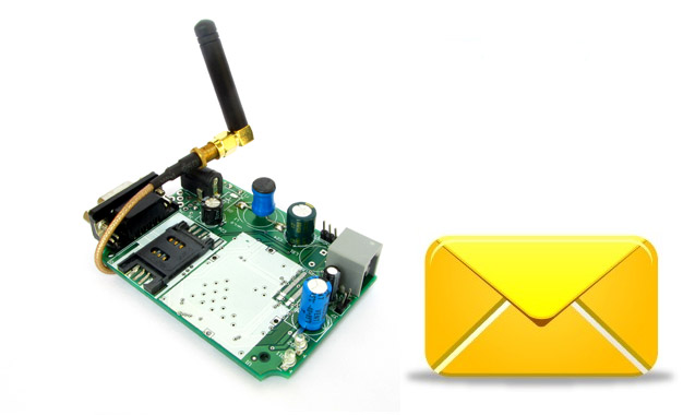
If you want a live demo of this, please register from the link given below. (Only in Pune) REGISTER NOW! This project can also be implemented using a PIC18F4520 microcontroller. We have schematic and C library available. Hi friends in this part we will have a look at the functions related to text messages. By the end of this article you will have a clear idea of how to wait for a text message, read the message, send a new text message and deleted a received message. We have already discussed the basics of SIM300 GSM Module interface with AVR MCU in our previous tutorial you can refer that article to know about the schematic and basic communication code. GSM Module SIM300 Interface with AVR After reading the above article you will know how we have connected the SIM300, AVR ATmega32 and LCD Module to make a basic test rig. Also covered in the article is the detail about the communication method between SIM300 and AVR which is called asynchronous serial communication, done using AVR’s USART peripheral. The article shows you how to use the AVR USART library to send and receive data to/from the GSM Module. We have also discussed the command response method used for the interfacing with the module. Working code is provided that shows you how […]

PC Controlled Robot

In this tutorial we will discuss a simple PC controlled robot. The Robot PC link will be a RS232 serial line. The robot will have only five commands. Move forward (RS232 char ‘F’ or ‘f’) Move backward (RS232 char ‘B’ or ‘b’) Turn Left (RS232 char ‘L’ or ‘l’) Turn Right (RS232 char ‘R’ or ‘r’) Stop (RS232 char ‘S’ or ‘s’) To keep things as simple as possible, in this example we will use terminal software RealTerm for sending commands to the robot. Later on a dedicated software can be written on PC end to control the robot. The Robot’s Hardware The robot’s hardware will be a simple differential drive using two 200RPM DC Gear motor mounted on a HQ Metal Chassis with a front castor wheel. On the back motors we have mounted plastic wheels. More about differential drive is explained in this tutorial. Gear Motors   Wheels   Metal Chassis   Remove motor’s nut   Insert the motor   Fasten the nuts again   Both motors installed   Front Castor wheel   Installing the front castor   Mounting hole for wheels screw   Mounting the wheels   Chassis is ready! The Electronics The robot is controlled using xBoard v2.0 which has ATmega32 as main CPU and integrated motor drivers. We have connected xBoard v2.0 with PC using […]

DS1307 I2C RTCC Interface using SoftI2C lib

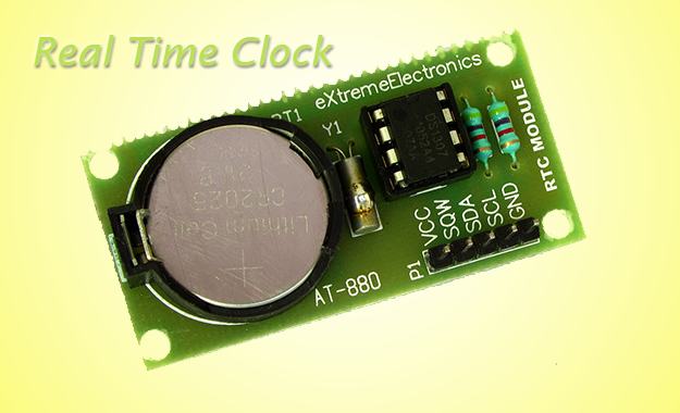
In the last tutorial, I explained you how to use our SoftI2C library to read and write a 24CXX series I2C EEPROM. Now I will continue our exploration and write a register access layer for the DS1307 chip. The DS1307 chip is a real time clock and calendar IC. The register access layer that we will develop provides the application programmer with function that reads and write the registers of DS1307. Remember that any piece of hardware appears to the CPU as a set of registers only. DS1307 has :- Seven Registers (from 0x00 to 0x06) that are used for timekeeping functions. One CONTROL register(0x07) for square wave generation setting (we don’t use this for simplicity). 56 bytes of battery backup RAM (from 0x08 to 0x3F) Fig. : A Simple DS1307 RTC Module.   Once the application programmer has access to functions that reads and writes to any register (specified by its address) inside DS1307 ic, he/she can easily get and set the time infos like sec,min,hour, am/pm, date,month,year etc. The register access layer is built over the core Soft I2C layer. The register access layer consists of the following three functions. void DS1307Init(void) { SoftI2CInit(); } /*************************************************** Function To Read Internal Registers of DS1307 ——————————————— address : Address of the register data: value of register is copied to this. […]

AVR Graphic LCD and Accelerometer Demo

Hello All!, Accelerometer applications are hot these days. So today I will show you how you can easily make a accelerometer add on for your AVR GLCD Board. Once you make this you can plug it into the AVR GLCD Board any time you wish to run a accelerometer based application on it. I will also provide a simple Open Source App for the AVR GLCD Board that can be used to test the accelerometer in no time. Developers can use this demo as a base for any accelerometer based app. Things you will need are A Veroboard or general purpose prototyping PCB (dotted one, not the line one). Female Burg Strips Female Burg Strip R/A MMA7260 Accelerometer Board Fig.: A Veroboard Marked for Cutting   Fig.: Veroboard Cut to Size   Fig.: Burg Strip Female   Fig.: Burg Strip Female Soldered to Veroboard.   Fig.: Burg Strip Female Soldered to Veroboard.   Fig.: 5 PIN Burg Strip Female Right Angle   Fig.: R/A Burg Strip Soldered.   Fig.: Just Ready!   Fig.: AVR GLD Dev Board   Fig.: Accelerometer Expansion Board Connected   Fig.: Accelerometer Connected.   Fig.: Accelerometer Connected with AVR GLCD Board   Fig.: AVR Accelerometer Ready! Connections     CONNECT TO GND Ground Supply Ground (EXP Port) VDD 3.3 V OUT SLEEP Sel2 G Select Pin2 […]

4×3 Matrix Keypad Interface – AVR Tutorial

Many application requires large number of keys connected to a computing system. Example includes a PC keyboard, Cell Phone keypad and Calculators. If we connect a single key to MCU, we just connect it directly to i/o line. But we cannot connect, say 10 or 100 keys directly MCUs i/o. Because :- It will eat up precious i/o line. MCU to Keypad interface will contain lots of wires. Buy Matrix Keypad We want to avoid all these troubles so we use some clever technique. The technique is called multiplexed matrix keypad. In this technique keys are connected in a matrix (row/column) style as shown below. Matrix Keypad Basic Connection The rows R0 to R3 are connected to Input lines of Microcontroller. The i/o pins where they are connected are made Input. This is done by setting the proper DDR Register in AVR and TRIS Register in PIC. The column C0 to C3 are also connected to MCUs i/o line. These are kept at High Impedance State (AKA input), in high z state (z= impedance) state these pins are neither HIGH or LOW they are in TRISTATE. And in their PORT value we set them all as low, so as soon as we change their DDR bit to 1 they become output with value LOW. One by One we make each […]

RF Communication Between Microcontrollers – Part III

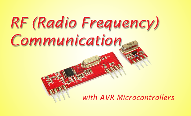
Welcome to the 3rd part of RF Communication tutorial. In the last two parts I have introduced the basics of RF Communication. RF Communication Between Microcontrollers – Part I : Introduction to RF Communication and Modules. RF Communication Between Microcontrollers – Part II : Algorithm and general description of data transfer. Part III will be covering mostly the practical part, i.e. we will build a complete & working data transfer system. Here you will get circuit and program to implement the solution. The application is very simple in this case, just to transfer a byte of data from Tx station to the Rx station. Once you implement it and get it working you will have enough information and experience to make other RF based projects. I request all users to follows the instruction exactly as given (unless they are smart enough to know what they are doing). The most important thing in this article is timing of the MCU, so Use the exact frequency crystals as used in the designs. Write High Fuse = C9 (HEX Value) and Low Fuse FF (HEX Value) to enable external crystal. Hardware We will have two units. One is Tx (Transmitter) and Other is Rx (Receiver). Both units are based around ATmega16 MCU(you can use ATmega32 also) on external 16MHz crystal. On the Tx […]

AVR Development Board – Assembly Instructions

A well designed development board is always essential for smooth development/experimentation with microcontrollers. Every hobbyist must have some kind of development setup. Some people use breadboard while others use veroboard to fabricate their development system. Many also use ready made off the self development board. Development is not very easy if you use only bread boards or veroboard. If you use bread board, after few days of use the wire will become loose or come out of hole. While making large circuit in a veroboard is a tedious job. To solve these problem I decided to make a low cost development board that has the following features. Low Cost All Basic connection required for developing application with AVR MCUs A Serial Port Prototyping area (like a veroboard) Incircuit Programmable with USB AVR Programmer Supports 40 PIN MCUs like ATmega16 and ATmega32. Buy Fully Assembled and Tested AVR Development Board So if you use this board, its lots easier. The basic circuit for MCU (like power supply,reset,ISP,serial port etc) are already done on a high quality PCB and some space is left for you to add other project specific components. You can also design other part of your project in bread board. But this time your bread board will be lot cleaner as major tested circuit is on the development board. […]