A well designed development board is always essential for smooth development/experimentation with microcontrollers. Every hobbyist must have some kind of development setup. Some people use breadboard while others use veroboard to fabricate their development system. Many also use ready made off the self development board. Development is not very easy if you use only bread boards or veroboard. If you use bread board, after few days of use the wire will become loose or come out of hole. While making large circuit in a veroboard is a tedious job.
To solve these problem I decided to make a low cost development board that has the following features.
- Low Cost
- All Basic connection required for developing application with AVR MCUs
- A Serial Port
- Prototyping area (like a veroboard)
- Incircuit Programmable with USB AVR Programmer
- Supports 40 PIN MCUs like ATmega16 and ATmega32.
- Buy Fully Assembled and Tested AVR Development Board
So if you use this board, its lots easier. The basic circuit for MCU (like power supply,reset,ISP,serial port etc) are already done on a high quality PCB and some space is left for you to add other project specific components. You can also design other part of your project in bread board. But this time your bread board will be lot cleaner as major tested circuit is on the development board. The development board has all PORT pins on female headers. You can connect to these using standard single strand hookup wires.
To make this ease of development available to all I am selling the bare PCBs so that you don’t even have to fabricate it on your own. The PCB is of very high quality with clear silkscreen layer(the top white labeling layer) and tin plated copper layer. In this article I will show you how you can assemble the PCB on your own.
Lets Get Started.
Always solder the low height components first. So we will solder the jumper wires first. Their are eight jumper wires labeled jump1 to jump8. Use any conductive wire to make the jumpers.
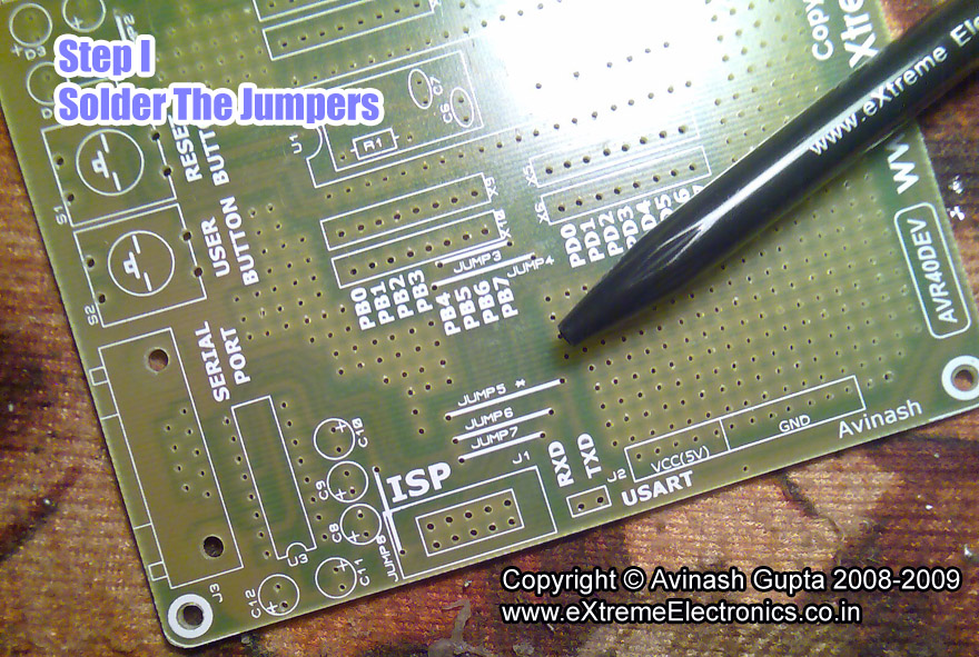 |
Fig.: Solder Jumper Wires |
After that solder 3 resistors
- R2 = 330 ohms
- R3 = 330 ohms
- R1 =4.7K
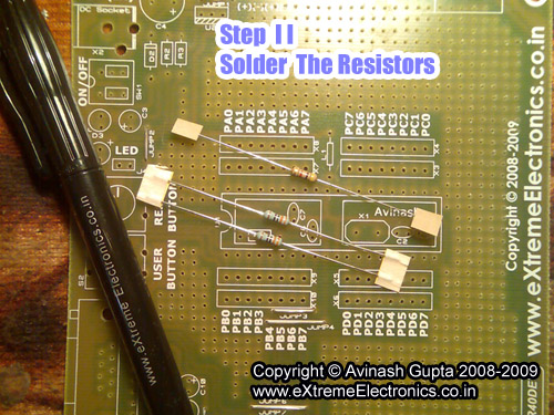 |
Fig.: Resistors |
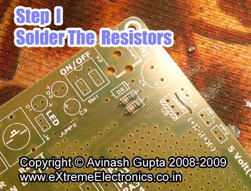 |
Fig.: Resistors |
Solder Inductor and Diode
- D2 = 1N4007
- L1 = 10uH
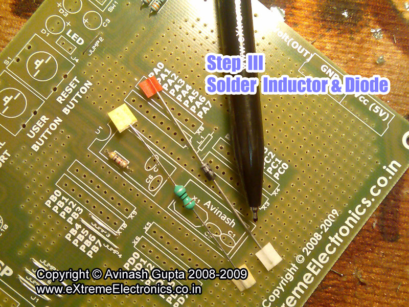 |
Fig.: Inductor and Diode. |
Continue by soldering the 5 ceramic disk capacitor.
- C1,C2 = 22pF
- C6,C7,C5 = 0.1 uF
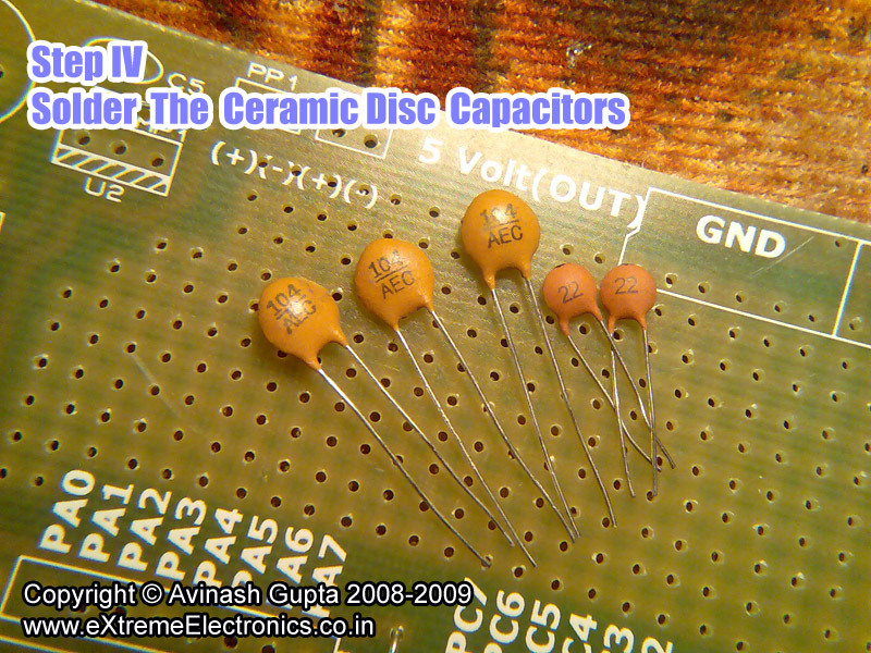 |
Fig.: Ceramic Capacitors. |
Now Mount the 2 IC Sockets
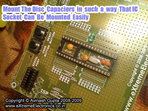 |
Fig.: Mount IC Sockets |
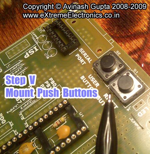 |
Fig.: Push Buttons |
After soldering the IC socket, solder the DC Jack, Power Switch,LEDs, Push Buttons, FRC Box Header and DB9
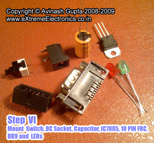 |
Fig.: Various Components |
Break the female headers in group of eight and solder them in 4 PORTs (A,B,C,D)
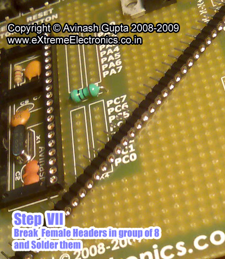 |
Fig.: A 40 PIN Swiss Machined PIN Female Header. |
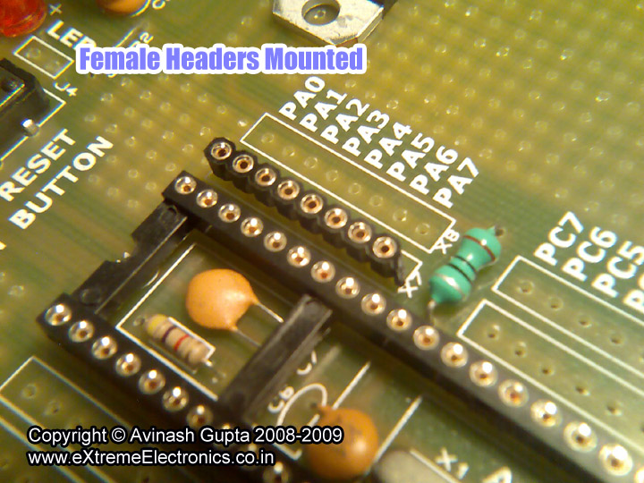 |
Fig.: Female Headers for MCU Ports. |
Now add 3 NOS 2 PIN Male Headers.
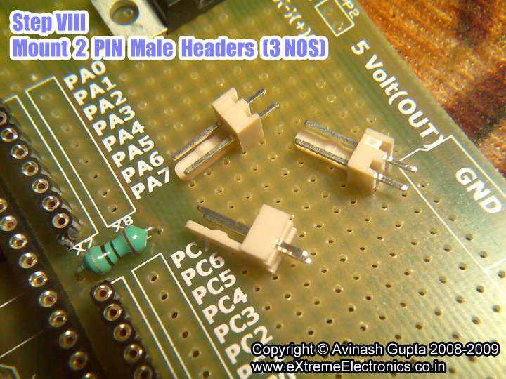 |
Fig.: Install Male Headers |
Now you’re done ! Time for some safety testing.
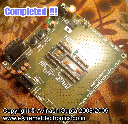 |
Fig.: Completed |
First Power up the board using a 12v 500ma adaptor
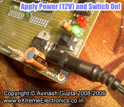 |
Fig.: Power Up |
Take a digital multi meter and check voltage output on extra 5v pins. It must be close to 5v.
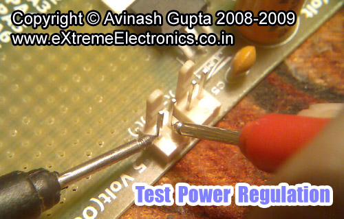 |
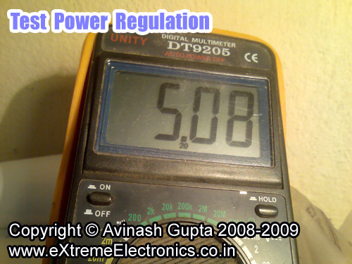 |
Also test the power supplied to the MCU. Test Voltage levels between the following pins
- PIN 10 and 11
- PIN 30 and 31
They must also be close to 5v.
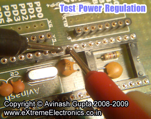 |
If all test are positive your development system is ready to rock! In the next part I will show you how to download the test program to the board to verify that everything is working perfectly. Till then good bye.
You can buy a fully assembled and tested AVR Development board from our shop. This board is 100% compatible with our USB AVR Programmer V2.0 hardware and eXtreme Burner – AVR software.
If you need this PCB in bulk for your college workshops we can give heavy discounts! Please call 0657-2442613.
Facing problem with your embedded, electronics or robotics project? We are here to help!
Post a help request.
Avinash
Avinash Gupta is solely focused on free and high quality tutorial to make learning embedded system fun !
Follow Me:


dude u are really raising the bar when it comes to affordable robotics.
why don’t u get involved in the ARP if u aren’t already.I cant see them getting any cheaper than this
To Mr. Avihash,
Really very effective and innovative idea for hobbyist, can you provide ZIF socket in pace of IC socket. can you provide same type for PICs also
PIC Development Board already available here
http://shop.extremeelectronics.co.in/product_info.php?products_id=79
For 40 PIN ICs like
PIC18F4550
PIC18F4520
PIC16F877A
Hi,
I need the PCB. Please let me know about the methods of payment.
I’ll inform you my mailing address after getting your reply.
Thanking You.
Regards,
Satya
Hi Avinash, Good job!
can i get ATmega32 dev board with LCD,UART,RTC etc?
if yes how can i get it?
pls reply
Regards
Gurushant Karki
Hi Avinash,
I am totally new in this.
I want dev board of ATmega8 with LCD,UART,RTC etc.
if yes please help!!
waiting for your reply!!!!
@ Sachin
I AM FED UP WITH THESE, PEOPLE DO NOT ANY THING ON THEIR OWN JUST START ASKING!!! 🙁
SO I DON’T REPLY TO THEM
PLEASE PLEASE FIRST TRY TO FIND THE INFO YOU ARE LOOKING FOR.
EVERY THING IS WRITTEN SOME WHERE AND THATS TOO VERY NICELY
Cool site, love the info.
hi,
Awesome work buddy….. i need tht board alone i got the components….. jus need to place and solder them on ur board…. how do i get them???? plz do inform the shipping procedure…
“need the PCB that cost is Rs. 99 including shipping any where in India by World Class Courier Service”
@Nirmal
Just give me a mail with your address [avinash[at]extremeelectronics.co.in [at]=@ and make payment of rs 99 as descibed here
http://shop.extremeelectronics.co.in/shipping.php
hi,
exxcellent work…..
is this pcb with the components u told to solder in the board sufficient to burn program in to a at8/16 using isp…. or any other seperate circuitry need????? and also waht is the use of tht female header??? grouped in to 2 8’s??? ie x5,x6,x7,x8,x9,x10?? waht r they??? plz do reply soon
Hi,
Mr avinash i want a pcb board on which i want to test the circuit of pcb having timer controller ic . so , can u give me the information regarding this aspect.
Hello Avinash SIR,
I am ATUL SINGH a junior OF ASHUTOSH UPADHYAY SIR who is the owner of ROBOlabz.
ASHU sir have told me about you so in that reference I would like to purchase a AVR development board from you.
Kindly mail me all the details and the procedure of purchasing as soon as possible.
Waiting for your reply………….
THANK YOU SIR
hello,
can u please explain the j1 part of the uC?wat is it?
@Gaurav
J1 is ISP header. The incircuit programming point. Its where you connect a ISP programmer to download programs to board.
II have a Really amazing site herePleasure to look at your site,
Thanks for the useful information. Can you please let me know where all can we use this AVR development board?
Hi Avinash!I received the USB AVR ISP and development board for ATMega32!!! I am amazed of the competitive price of yours and am also stunned by the pack that contained everything for a beginner!I ll surely encourage students to visit your site!
Thanks a lot man!
@Mr Prem Sunder
Kind words like yours is our Only Inspiration !!!
Thanks for your testimonial.
what is the cost of this avr board. please send the details of this avr board to my email id. i want to purchase this avr board.
Hello Avinash sir,
I found your board amazing!… I want to buy the board…
plz send me the details….
@Pranav
Get it from here
http://shop.extremeelectronics.co.in/product_info.php?cPath=23&products_id=98
GOOD JOB AVINASH JI. You explained all the things in such a way that they become very easy to us. Keep it us. please give us tutorial on how to interface 5×7 dot matrix & how to make a scroll message board using it.thankyou for your tutorial series……………..
Hi..
First i wanna appreciate you for your awesome work bro! “Hats off!”
.
you haven’t mentioned when to mount the crystal osc in the circuit (and also its specifications) please, clarify that too.
Hey! Avinash,
ur tutorial is good.I made the devlopment board, but it didn’t work.Can u just make me familiar with the conditions under which the board may not work, and the necessary prcautiions that must be taken while making the dev board…so that it is a success.
i need the user manual for this board
Is there an easy tutorial on serial interface using AVR Development board !!
Please advise.
I tried to make development board. Its working fine. But
there is a problem that PIN
PC5 (TDI)
PC4 (TDO)
PC3 (TMS)
PC2 (TCK)
in atmega16 is not working properly. I tried twice with two different board and two different Atmega16 but same problem. Please help.
@Vijay,
Please give your Order ID, Type of programmer hardware and software you are using.
.i am using your USB programmer, software are extreme Burner Avr Programmer (V 1.2), AVR studio 4. I made development board on VeroBoard by the help of tutorial given by you.
Go to “Fuse Bits/Settings” Tab, Click “Read All”, Under “High Fuse” click “Bit Details …” change bit no 6 (JTAGEN) to UNPROGRAMMER(0). Make sure “Write” check box is checked, then click Write. This will disable JTAG and free those pin.
thanks a lot for help. i goggled it and found that i am doing one more mistake . i was not configure for external Crystal also. so i found to configure low fuse as (FF)and high fuse as (C9). i am using 16Mhz crystal, so i am willing to ask weather this configuration is correct for 16Mhz crystal. i am having fear of loosing Atmega as there was written to take precaution thats why i asked.an yes can we change confugration again in future..??
@Avinsh : thanks a lot…. 🙂
hi! Your work is awesome. I need to know one thing that may i have interfacing diagram of LCD with 40 pin AVR ATMEGA32 development board. I research a lot on this site and i found LCD interaction with 28 pin AVR MCU. ONly one pic i found which shows LCD with 40 pin ATMEGA32 but it’s for 4 bit transfer. Other 4 pins are open. Why??? I need LCD interaction with 40 pin AVR ATMEGA32 development kit. I have assembled it and now facing problem to connect LCD. PLS pls pls reply me soon.
this is amazing
Hi Avinash, kudos, I really appreciate your site is flourishing, I shopped for 10 AVR40DEV boards and other for developing on various projects in mind from your AVR platform board – can you provide gif schematics of your board to connect different AVR mcu’s. Also I scoured & googled to find Indian shop for “40 PIN Swiss Machined PIN Female Header” or machined IC sockets 40pin,28pin,14pin,16pin,8pin – I feel sad that most local as well as online shop stock clip type sockets and headers which soak slime of acetone-flux wash-off — can you give me some links as to where to procure the machined sockets? Also the GLCD I bought from you are 8bit when do you propose to stock SPI based GLCDs?
Hi Avinash,
Great work. I am too lazy to do soldering stuff. This board is simply superb and any other cannot go cheaper than this. I am back to my old MCU days because of this.
Keep rocking 🙂
Cheers,
Sundeep
@Sundeep Subbaraya
Thanks
Hi Avinash,
I received the board. After playing with Arduino IDE for one hour, I was able to burn arduino bootloader and upload sketches to board. With Open Source software and your board my life has became much easier. If you agree I can post this info and pics on your facebook page. Hope this would be helpful for some guys 🙂
Cheers,
Sundeep.B.S.
Sir thank you for atenstion me.May i get the free sample.