Know your xBoard MINI
xBoard MINI v2.1
Easy to Use learning and development tool for Atmel AVR family of MCUs.
Back |
Support |
Store |
Facebook |
xBoard MINI v2.1 is an advance development board for 28 PIN Atmel AVR MCUs like ATmega8, ATmega168 etc. Beginner can use it as a tool to learn microcontroller programming while advance user can use it as a base for complex project. The advantage is that you get a fully tested and well designed board with many peripherals. The tutorials guide you from the very beginning and covers most commonly used techniques useful for embedded projects.
The board is designed so as to reduce the mess to minimum. The board has everything on board to reduce external wiring during the first learning period. This ensure maximum positive results during initial experimentation.
Huge amount of fully debugged and quality C sample code can serve as a base for numerous projects. This make tasks which seems impossible to beginner, very easy to accomplish.
Unlike others we are not selling just the board. What is more worthy is the bundled tutorials and codes specifically designed for the board. These tutorials gives you a very smooth path to reach your goals. Add to these the Full-fledged, Industrial Strength Projects supplied with the board, these serve as a treasure house of knowledge. These can be quickly modified to your need and deployed as a solution!
Features
- ATmega8, ATmega168 ready (28 PIN AVR Device)
- Built in 16MHz Crystal, 5v regulated power supply, reset button,on/off switch, LC Circuit On AVcc for clean ADC operation.
- In-circuit Programmable by any ISP Programmer like USB AVR Programmer v2.1
- 1 User LED.
- 4 User push buttons.
- Serial Port with TTL and RS232 output (MAX232 Circuit Inbuilt)
- 16x2 Alphanumeric LCD Module.
- NEC Format Remote Control Receiver(TSOP1738) and Decoder(Software library).
- Philips RC5 decoder software library (COMMING SOON).
- DS1307 based Real Time Clock with coin cell backup.
- LM35 Temperature sensor.
- xAPI - Easy to use C Library functions to do common tasks.
We recommend you to read the more basic and general topics from here.
http://extremeelectronics.co.in/category/avr-tutorials/page/3/
NOTE: The user is assumed to have basic knowledge of general programming techniques, knowledge of C programming language, Basic operations of a computer, basics of analog and digital electronics and most Important, a will to learn! Please don't ask the following.
- What is a compiler?
- Can I burn a C file directly to MCU?
- What is 0xFC?
- What is logic high?
- I can't see hidden files in my computer!
- What is a file?
- How I start my computer?
- What is a computer?
OnBoard ?
 |
Onboard hardware. |
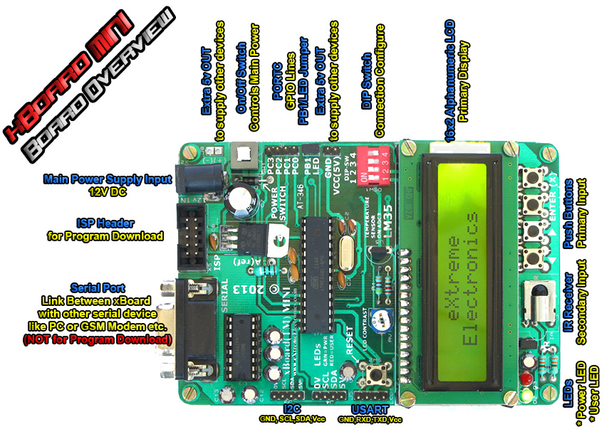
- Main Power Supply Input : Standard DC socket for powering the board. Use a 12v 1A adaptor with Center positive pin. Compatible adapter is supplied with the package.
- Extra 5v Output: When you attach some other peripheral to the development board, this point can be used to supply that peripheral with regulated 5 volts.
- On/Off Switch: Main Power Control, used to turn on/off the entire board.
- PORTC GPIO Lines: PORTC i/o pins. PC3, PC2, PC1, PC0.
- PC3 is internally connected to push button (named X or delete), it is also analog input channel 3 so is also connected to temperature sensor (LM35). To use PC3 for other purpose, turn off DIP Switch 3. This will disconnect PC3 from temperature sensor and free it for other use.
- PC2 is internally connected to push button ENTER. If you use PC2 for other purpose (i.e. connect externally to some peripheral) DO NOT PRESS ENTER KEY WHILE IN OPERATION.
- PC1 is internally connected to push button RIGHT ( > ).If you use PC1 for other purpose (i.e. connect externally to some peripheral) DO NOT PRESS RIGHT KEY WHILE IN OPERATION.
- PC0 is internally connected to push button LEFT ( < ).If you use PC0 for other purpose (i.e. connect externally to some peripheral) DO NOT PRESS RIGHT KEY WHILE IN OPERATION.
- JP2: Used to connect the User LED to MCU's PB1. When not using onboard led you can disconnect the LED by removing the jumper. Then you can freely use PB1 pin of MCU for your own application.
- Extra 5v Output: When you attach some other peripheral to the development board, this point can be used to supply that peripheral with regulated 5 volts.
- DIP Switch:
- Switch (1) (2): On= RTC Connected to MCU. If you want to disconnect the Real Time Clock from MCU then switch off 1 and 2. Then you are free to use the ports PC4(SDA),PC5(SCL).
- Switch (3) : On = LM35 connected to ADC3(PORT PC3).
- Switch (4) : NOT USED.
- 16X2 Alphanumeric LCD Module: This is a standard 16 character by 2 lines LCD module.
- Push Buttons: Connected to PORTC (PC0,PC1,PC2,PC3)
as shown below. The PORTs must be set to INPUT mode with Internal Pull
ups enabled. When a button is pressed it will cause the associated line
to go LOW.
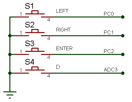 Buttons Schematic
 - IR Receiver: Used to Interface with Remote control. An easy to use remote control library is provided to decode a standard NEC protocol remote control.
- JP1: Connect/Disconnect the IR Sensor from INT0 of
MCU. If IR Sensor is not required you can remove this jumper and utilize INT0(PORT
PD2) for your own use.
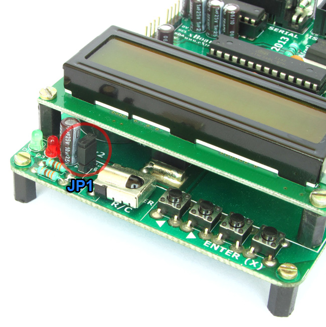 JP1 Connects INT0 with IR Receiver (TSOP1738)
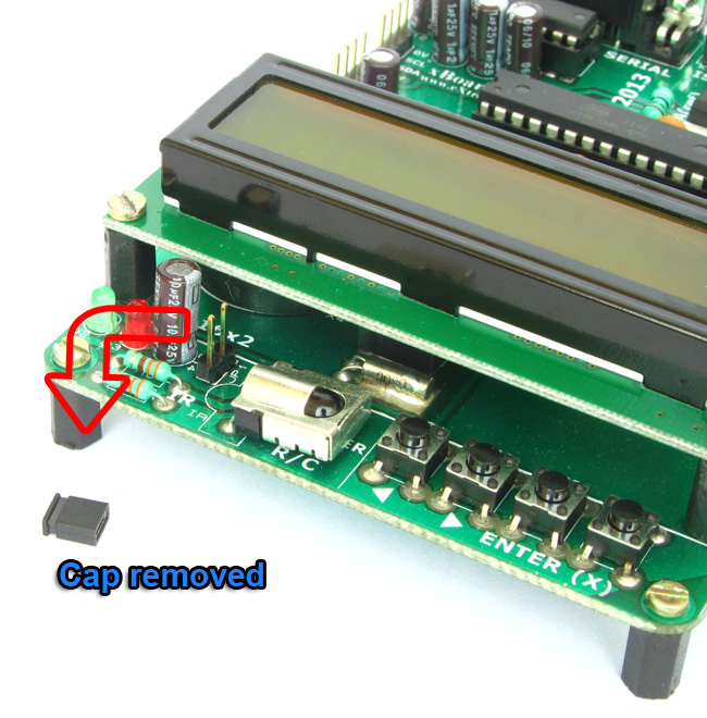 JP1 Cap Removed
 - User LED: This LED is connected to PB1 (Port B, Bit 1). You can write '0' to PB1 to make the LED light up. You can remove JP2 to disconnect LED from PB1.
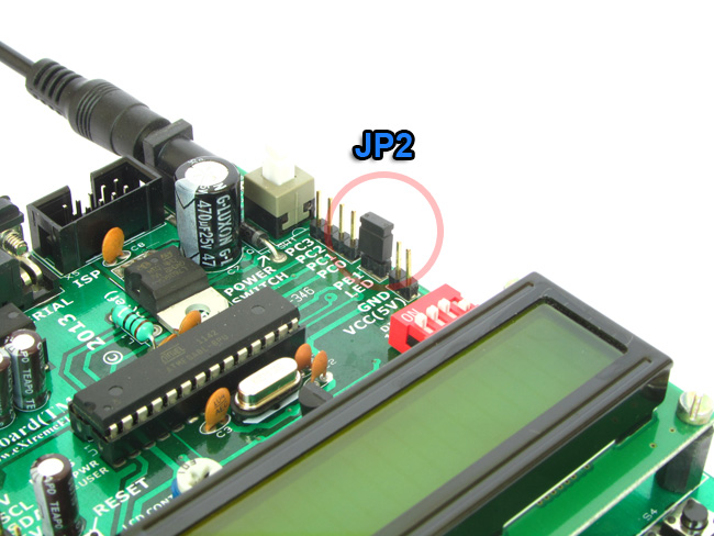 JP2 Connects PB1 with USER LED
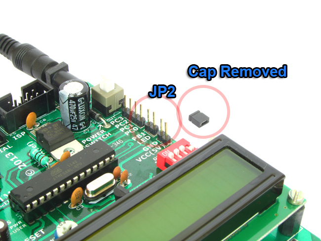 JP2's Cap removed
 - Power Indicator LED.
- USART: TTL Level USART signals. Connects with any USART based device like Mobile phone,GSM Modem,GPS, RFID etc.
- I2C Port1 and Port2: I2C Bus is a popular Inter IC communication bus. You can use it to hook up a number of I2C peripheral like PORT expanders, memories, radio chips and more. Use the simple I2C functions to transfer data.
- Serial Port: RS232 Level USART signals. Connect to PC and use simple function to send /receive data to/from a PC. PLEASE NOTE THAT THIS PORT IS NOT USED TO PROGRAM THE BOARD!
- LM35: A standard temperature sensor chip. Connected to ADC3 and can be disconnected by DIP SW 3.
- ISP Header: This is used to update the program of the MCU without removing it from the board. See this article for more informtaion.
Need More ?
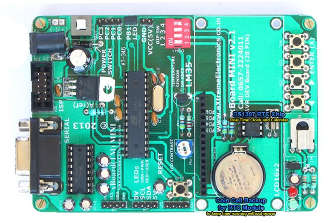 |
Real Time Clock Module with
DS1307 chip. |
A complete RTC module is built into the board. The RTC is based around the popular DS1307 chip. The battery backup keeps clock running even if the board is switched off and placed in the cupboard for 10 years !
Back |
Support |
Store |
Facebook |