This article series aims at teaching serial communication between a PIC microcontroller and a PC. We first introduce you with what is serial communication is and how it can used. Then we tell you how to perform serial communication using PIC microcontroller and how we use the USART peripheral for the purpose. We will tell you how our usart library for PIC16F series can be used for easy serial communication, in this part we also discuss how to set up a MPLAB X project for using the USART library. After that we will build a demo project to explore the library. Finally we will burn this demo in a PIC16F877A and establish a serial communication with PC.
Serial Communication
Their are several serial communication standards like RS232, SPI, I2C etc. Of which RS232 is a asynchronous method. That means it does NOT have a synchronizing clock line. One way data requires only one conductor line. Since it is a two way communication their are two lines between the two device. One for sending data called the Tx and one for receiving data called the Rx.
The communication is full duplex, that means data can be sent at the same time data is being received.
generally other serial communication like SPI and I2C are used for short range communication like between two ICs placed on same board or system. While RS232 based serial communication is used for short range as well as long range communication (cables length longer than 2 meters).
High voltage input output and requirement of fewer wires makes it ideal for long range communication.
PC’s Serial Port
In old days PC’s were equipped with a serial port since on those days many peripherals like modems and mice were connected using serial ports. But now a days they are replaced by USB ports which are much more advanced. But working with serial port is much easier from a designers point of view.
But their is no need to worry with the absence of serial port from PCs. You can purchase a USB to Serial Adapter to connect all your serial devices with PC using USB port!
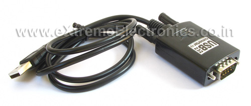
Fig. USB to Serial Converter |
Although as you can see from the image above a standard serial port connecter is a 9 pin d type male connecter, but only three pins are used for our purpose. You can see their position in the image below.
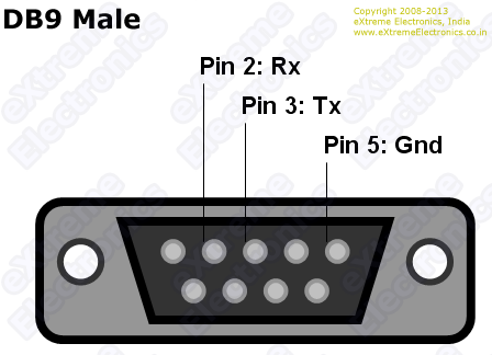 |
Fig. DB9 Male Pin out |
Connecting to DB9 Male
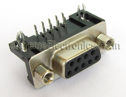
To connect your hardware with DB9 male of serial port you need a DB9 female connecter as shown in the image below.
Fig. DB9 Female |
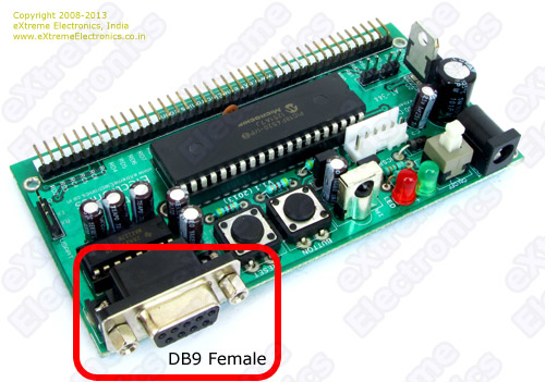
You can solder this connecter on your PCB to be able to connect with serial port easily.
Fig. DB9 Female on PIC 40 PIN Development Board |
Images below shows how easy it is to connect a USB to Serial Converter to the board.
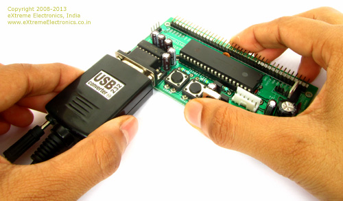 |
Fig. Connecting with Serial Port |
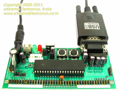 |
Fig. Serial Port Connected |
Level Conversion
At this point you should become familiar with a point that voltage level on RS232 line is different from the voltage levels generally used in microcontrollers and other ICs. So to interface RS232 level signals to our MCUs we need a "Level converter".
What a level converter will do is to convert RS232 level signals (HIGH=-12V LOW=+12V) from PC to TTL level signal (HIGH=+5V LOW=0V) to be fed to MCU and also the opposite.
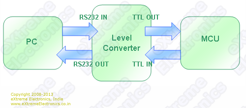 |
Fig. Working of Level Converter |
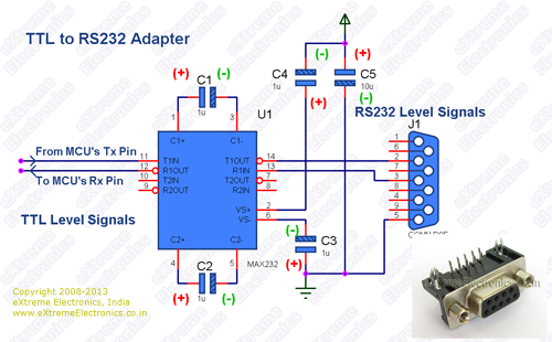
As RS232 is such a common protocol there is a dedicated IC designed for this purpose of "Level Conversion". This IC is MAX232 from Maxim. By using charge pumps it generates high voltages(12V) and negative voltages(-12V).
Schematic For Level Converter
Fig. Schematic for Level Converter. |
Bill of Material for Level Converter
| Reference | Value | Quantity |
| C1,C2,C3,C4 | 1uF 25 Electrolytic Capacitor | 4 |
| C5 | 10uF 25 Electrolytic Capacitor | 1 |
| U1 | IC MAX232 | 1 |
| J1 | DB9 Female R/A PCB Mountable | 1 |
PIC16F877A’s Serial Port
The serial communication pins of PIC16F877A is shown in the image below.
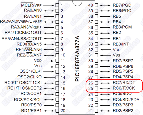 |
Fig. PIC16F877A’s Serial Port. |
You can see that pin 26 is RX pin while pin 25 is TX pin.
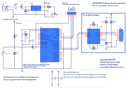
Complete Schematic for USART Demo
Fig. Schematic for USART Demo.(Click to Enlarge …) |
This article described only the hardware setup required for interfacing PIC16F877A with PC using USB to serial converter. The software part consisting of the USART library for PIC, its setup and use with MPLAB X IDE and XC8 compiler are described in a separate article.
By Avinash Gupta
www.avinashgupta.com
Facing problem with your embedded, electronics or robotics project? We are here to help!
Post a help request.



Mr. Avinash,
It is always nice to see new things in this site,expecting software part of this article soon.
Regards,
Uttam
@Mr. Uttam Dutta,
Thank you.
Pingback: USART Library for PIC – Setup on MPLAB X IDE |eXtreme Electronics
Pingback: PIC16F877A Serial Communication Demo |eXtreme Electronics
i want to know more about spi communication in pic…
I don’t have money much enough to buy a starter kit.I like to connect the pic directly to pc using level controller.Is it possible to do so.If yes please send me the circuit diagram to connect in such a manner
Hi Avinash
Do you have and project with SENT Protocol?
Hi Avinash,
I would like to introduce you to the scm which is an alternative library to rxtx/javaxcomm for serial port communication.
Wiki : http://www.embeddedunveiled.com/
Repository : https://github.com/RishiGupta12/serial-communication-manager
Video : https://www.youtube.com/watch?v=fYLQbelGunQ
It supports RS-232 control signals handshaking, monitoring and has been ported to Linux, MAC, Solaris and Windows operating system. It is consistent, portable, efficient, reliable, testable, extensible, modifiable, scalable library.?
What is the max length of two device for serial communication.