Hello Friends,
Welcome back to the Part II of RF Communication tutorial. Here I will show you the basic working of RF modules and how to send and receive data. Please see the Part I of this tutorial for basic introduction. You should also be familiar with RS232 communication. If you are new to it please see RS232 Serial Communication Tutorial. I also recommend using wireless link only after you have successfully tried wired RS232 communication. Here I will not go deep in how RS232 works because it is already discussed in RS232 Serial Communication Tutorial. I will use my interrupt driven fully buffered USART library for communication.
How RF Module Works
Working of RF Modules is simple but with a little trick. The working is shown in figure below.
|
Fig- Working of RF Modules. |
Here what ever digital data you input on "Data In" of TX is available on "Data Out" of RX. Say, if you set "data in" high, the "data out" will become high as well. But here lies the trick! The fact is that you cannot Keep Logic HIGH or LOW for a Long period of time, say for a few millisecond second. If you apply a logic low on "data in" the "data out" will become low but only for few millisecond and it will start oscillating(become high/low repeatedly) after that. Same thing will happen if you set "data in" to high state.
Let us assume we have connected the RF modules with MCUs as shown below.
|
Fig- RF Modules connected to USART of Microcontrollers. |
When the TX unit is switched off or not transmitting data, then as I said the "data out" of RX will be oscillating high and low and as this is connected to RX of MCU’s USART, the MCU#2 will be receiving garbage data. And when TX unit will send some data, MCU#2 will also be receiving them. So MCU #2 is always receiving data,even when MCU#1 is not sending anything. So their must be a mechanism to differentiate real data with garbage data.
Sending and receiving data.
For this I created a simple mechanism. The steps are shown below.
- We begin transmission by sending character ‘A’
- We again send one more ‘A’
- Then we send the actual data.
- Now we send the inverse of data. That is all 0’s are converted to 1 and vice-versa.
- We end the packet by sending ‘Z’
In this way we create a simple packet based transmission with error detection. Now in the RX side MCU our program follows the algorithm given below.
 |
Fig- Data Reception Algorithm. |
If we went to the end of algorithm successfully it means that we have got a valid data and we can use it.
So in this way we saw how a byte of data is transmitted from MCU#1 to MCU#2 via air. This simple algorithm filters real data from garbage data. In the next tutorial we will see the practical example of data transmission and reception. We will use the received data to control the IO ports of MCU, in this way we will create a simple multi channel wireless remote control.
By
Avinash Gupta
me@avinashgupta.com
My Facebook Profile
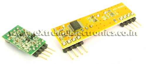 |
RF Modules |
Pingback: RF Communication Between Microcontrollers - Part I | eXtreme Electronics
pls pls be fast in providing us da 3rd part dude pls……dis da only site we look at for avr pls dude do it fast……..
good tutorial,
but still,there is one shortcoming in your algo,which is time synchronisation which has not been discussed.Ie how does the receiver know when shud i expect which data.i know that is not an issue,but at high data rates,it does become an issue
And the circuit which i suppose u will be using ie direct connection will work fine for a max of say 800 to 1200 bps if u get lucky that is
Use a lm 324 in comparator mode with a Vref of around 2.8 to 2.9V .that solves the receiver oscillation as well as allows baud rates upto 2400
Karthik please tell me in details or give a diagram how to connect the LM324 with RF Receiver module
@Subhagato
No LM324 or anything is required. Wait for part III and everything will be clear.
@Karthik
Can you tell more about time sync and how u achive it? Because I have tested the above algo and it works well !
1 thing, I am searching from days that is it possible to receive data on 1 ASK RF Receiver from more than one ASK transmitters simulteneously? if not then how can i achieve it?
AFAIK you can do it. thats how broadcasts work
Finally I found someone who explains clearly about this RF modules and let us know about “the catch” or trick involved!
I previously had some “harsh time” trying to figure out how to transmit reliable data and was aware of the noise when not transmitting anything.
I hope next article show us some obscure details like voltage levels (I found better reception lowering the signal for transmission).
Thanks Avinash for another great article. Greetings from Mexico 😉
time sync is not a problem
Basically imagine u are controlling say 5 robots from your master receiver
And u are sending a packet of data
say for eg :
start id data1 checksum stop
now at a given time only one bots id is valid
so other bots have to “WAIT” till the complete transmission is valid,becuz they might and i mean might lose data incase their clocks are not reliable
typo sorry i meant master transmitter
dude just forget the time sync problem,sorry for being a party pooper and spoling the fun,i checked with an oscilloscope and saw that it is experienced if and only if the internal rc clock of 1MHZ is used
I want to receive on 1 receiver from more than 1 transmitters. NOT Transmit to more than 1 Receiver.
we ar very much awaited for ur rf communication between mc part-3 pls pls do it fast ……jus waitng for ur part-3 dude do it as soon as possible
when can we exepect ur part-3 of rf communication beween mc pls pls be fast be ar very much awaited for it
Hi !
Just a comment : yours tutorials are very good !
Continue please !!! :—)
I’m waiting for your next tuto 😉
Have a nice day !
dudee whn will u post ur part-3 jus waiting for it……….
man your tutorials are excellent.Its the first time i’ve seen them and i’ve allready become a fan….
hi, i want to do a engineering project using atmel uC in wireless systems(data acquisition or control)can u suggest me some good projects
thanks
dude we ar very much awaited for ur part 3 pls pls do it fast na ……………….pls dude getng bored wana try smtng new wid rf modules
fabulous tutorials…dude
thanx for helping all of us at this time…wen v require the info about microcontroller communication very much…
hi avinash..i m doing a project on wireless home security system…would be needing ur help and also when wud u be posting the third tutorial…thank u…
dude i am about to complete my b.tech can we expect ur part-3 before tht …………
sir,we have been eagerly waiting for the third part.its been almost three months since your last post.please consider our situatuion and the advantage we will gain in competitions if we master how to use thr RF modules.please take our situation under consideration and atleast complete the RF tuorial series.thanks.
Hi, Nice Post..
But Part 3 not yet submitted.
Check Below code..
#define RCV_DATA_VALID 1
#define RCV_DATA_INVALID 0
#define RF_HEAD ‘A’
#define RF_TAIL ‘Z’
typedef struct {
char rf_head1 ;
char rf_head2 ;
char rf_data ;
char rf_revdata ;
char rf_tail ;
}RF_Struct ;
RF_Struct g_rfData ;
/*********************************/
void FillValidData(unsigned char data) {
g_rfData.rf_head1 = RF_HEAD ;
g_rfData.rf_head2 = RF_HEAD ;
g_rfData.rf_data = data ;
g_rfData.rf_revdata = (~data) ;
g_rfData.rf_tail = RF_TAIL ;
}
/*************************************/
unsigned char CheckRcvValid(void) {
if(g_rfData.rf_head1 != RF_HEAD){
return RCV_DATA_INVALID ;
}
if(g_rfData.rf_head2 != RF_HEAD){
return RCV_DATA_INVALID ;
}
if(g_rfData.rf_data != (~(g_rfData.rf_revdata))){
return RCV_DATA_INVALID ;
}
if(g_rfData.rf_tail != RF_TAIL){
return RCV_DATA_INVALID ;
}
return RCV_DATA_VALID ;
}
/************************************/
/*for transmitter*/
void main(void){
unsigned char data = 10 ;
FillValidData(data);
/* next transmit block of data */
SCI_TxBlockData((unsigned char *)&g_rfData);
}
/************************************/
/*for receiver*/
void main(void){
while(!(SCI_RxBlockData();));
/* check your data must be available in g_rfData */
}
please post the part 3 of this post soon i need it urgently………..please
hello sir i need to connect RF Tx to serial port i mean rs232 using max232 is it possible and how can u explain clearly
plz sir post the third part….
Hi Sunny,
Ofcourse you can connect RX TX to serial port. if you want to communicate with PC then you need Max232 for TTL to RS conversion,otherwise you can directly connect TX RX to any electronic component(other MCUs) or RF modules etc.
Hi Avinash
I think you may include following points in above algo.
1. 433 RF module available in market does not use NRZ (UART uses NRZ)
encoding/decoding for transmitting and receiving data.
2. 433 RF module only understands Manchester encoded/decoded data.
They need manchester encoded data for transmission and
manchester decoded data at receiving end.
3. There are two solutions.
a) Either use chips like HT12E and HT12D for transmitting and receving data
respectively
MCU TX data to be transmitted via UART —-> HT12E –>RF transmiting module”’
””RF receving module—> HT12D —-> Original data recevied. through UART in RX pin of MCU.
b) Instead of using above HT12D and HT12E chips, you can encode and decode data
using Manchester algo implemented in your program.
If you have any suggestions, please let me know.
Thanks!
Brij !!!
we r waiting for th 3rd part !!!
Pingback: RF Communication Between Microcontrollers – Part III | eXtreme Electronics
Avinash Gupta
Hello ur RF communicaion tutorial is really Nice kindly post ur next quickly
@Sunder
Part III is already available
see it here
https://extremeelectronics.co.in/avr-tutorials/rf-communication-between-microcontrollers-%e2%80%93-part-iii/
why are we inverting and sending the data??
@SAV
Because the “idle” state of RS232 line is logic high. As we are using ASK transmitter which consumes power only when sending 1, so we don’t want to waste power when NO data is being sent. Thats why we are inverting.
Sir,
Continuing on what SAV asked, does that mean that we are assuming the data we send will contain more ones than zeros???…pls xcuse me if my doubt looks silly
Regards,
Abraham
Sir,
I got my doubt cleared when I read the third tutorial…thanx a lot once again for uploading such great references
Regards,
Abraham
Is the TX-RX module available under eagle, as a part? [Or can I download them from somewhere?]
@Shaunak De
I don’t use Eagle so have NO idea. But making the Device in any EDA package is just few minute job.
hello avinash, i want to ask , let say, i use analog sensor, then I try to send the data show by this sensor by using rf transmiter and received the data by receiver and activated the alarm.It is possible to do such that things?
fatimah it is possible.
Dear sir,
I doing my third year B.E and interested to a project based on RFID. I want to know about how the rfid reader transmit the information to rfid tag. Please give me the details with example application and how to program in ARM processor. I hope and expect your reply soon to mail ID. velu.crescent@gmail.com
Thanking you!!
@Velu,
Why ? I should do so much favor to you ?
-The Admin
thanks it is helpful to me
Dear Mr Avinash,
I went through the RF communication tutorials provided in your site and followed the algorithm and wish to write the same in 2051/8051 MCU for making multi channel RC kit. But I am having several questions and doubt in mind that :-
1.> Why are we sending two ‘A’ (Ascii mode) in succession ….why not only one?
2.> While the SBUF or serial buffer of TX MCU has sent one ‘A’ and next instruction is about to put another ‘A’ in the SBUF then there may be some overhead delay that can again lead to oscillating RX module for a brief moment and cause error…
3.> To minimize overhead delay can I use high freq clock or standard 11.0592 MHz clock adaptable for serial comm may be used??
Pingback: Using RF modules (433MHz) to send data | DostMuhammad.com
Good tutorials
Thanks
really very much helpful…thanks…
Very good explanation and idea. Thanks!
hello sir,
would u please help me to interface Rf module(Nrf24l01).Can we interface by using this tutorial??
can data be transmitted without microcontroller i.e,manually???
Can SPWM be generated using AtMega16 ??
what is SPWM?
Very much helpful.
i want to transmit data from microcontroller to PC wirelessly. and want to save in my database
Can i use rf communication?
if yes then how it would be ?
@Shraddha,
Use XBee modules for that.
bt i want a cheap solution
@shraddha,
Then use nRF series from Nordic Semi
Sir,
How can I use RF 434 with 8051 to tranmitt “hello” from transmitter side… I will be glad if you can help me out with circuit and most imp. Coding in C…