Atmel Studio 6
xBoard MINI v2.1
Easy to Use learning and development tool for Atmel AVR family of MCUs.
Back |
Support |
Store |
Facebook |
Atmel Studio 6 or AS6 in short, is the latest IDE (Integrated Development Environment) by Atmel for their 8 bit and 32bit MCUs lines. AVR Studio 6 comes integrated with latest version of avr-gcc compiler. So the complete development environment can be installed with a single, easy to use installer.
The IDE Consist of a high end editor with flawless auto-complete feature. The editor is powered by proven Microsoft Visual Studio. The editor makes it easy to type and edit C source file with its auto complete feature. the user don’t have to “refer” to the reference manual often, as the editor itself shows the parameter requirements of functions, its return type and a short help on functions.
Introduction to the Atmel Studio 6 Environment.
You can start Atmel Studio 6 by using its icon from the Windows® Desktop or the Start Menu.
|
Fig. 1 - AS6 Desktop Icon |
|
Fig. 2 - AS6 Startup Screen |
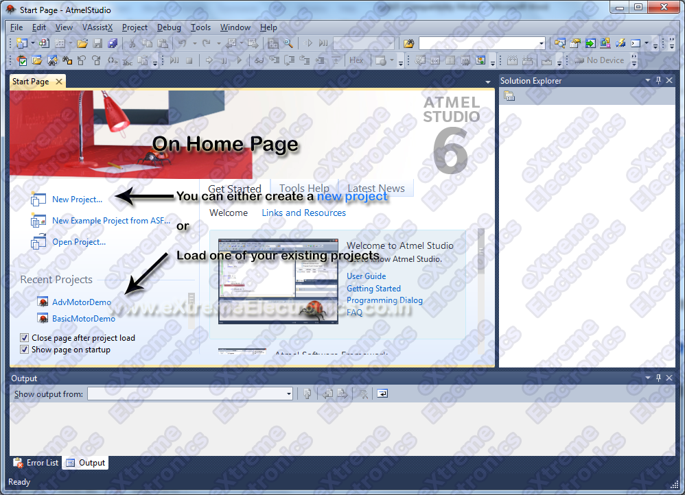
The First screen shown up after the AS6 has started is the Start Page. The start page helps you quickly create a new project or load your previous project without wasting much time.
|
Fig. 3 - AS6 Home Screen. |
Creating a New Project
To create a new project we select “New Project …” option from the Start Page. Please refer to Fig 3.
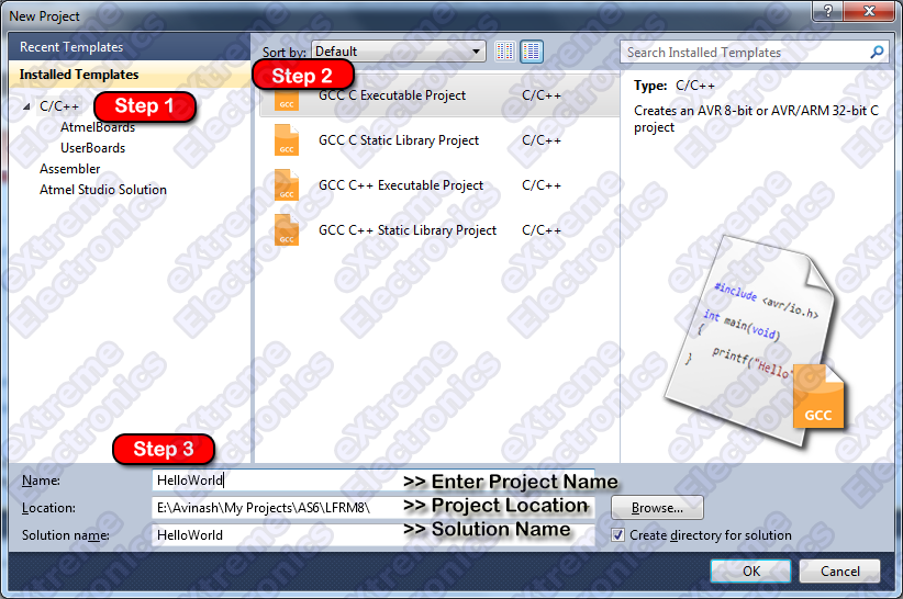
AS6 will show you the New Project Wizard as shown in the image below (Fig 4).
Step 1: From the project template area (Installed Templetes) select C/C++ as the project template.
Step 2: From the project type area select “C Executable Project” .
Step 3: After that fill out the project details at the bottom, like project name, its location on your PC etc. Finally Hit Ok.
|
Fig. 4 - New Project Page1 |
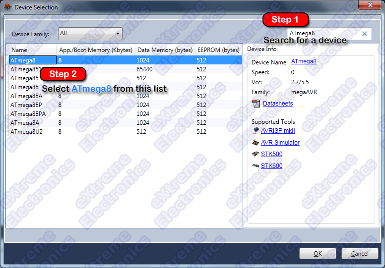
After the project detail window, comes the Device Selection Window. That let you choose the target MCU for your project. Here in our project we are using ATmega8 MCU so select that from the device list.
Step 1: Go to the search box and enter "ATmega8"
Step 2: Many chips whoes name begins with ATmega8 (like ATmega8515, ATmega8535 etc) are listed. Select ATmega8 (or whatever chip is present on your xBoard MINI)
Step 3: Click OK.
|
Fig. 5 - Device Selection. |
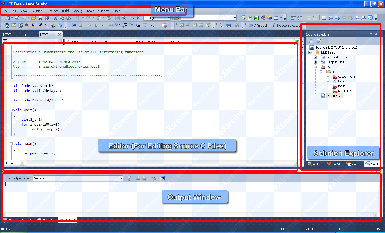
After we have completed the “New Project” wizard, we are presented with the AVR Studio 6 main window. So let us get introduced with the various parts of AVR Studio 6 window.
- The Menu Bar – Common in most windows applications. This has commands for all tasks organized in submenus like File , Edit, View etc.
- The Tool Bar – It is also common in most applications. The tool bar has selected commands from the Menu Bar which the user uses more often. They have small icons for each command.
- The Main Source Editor – This window is the main editor for the source files in the current project. you can load any file (in your current project) by double clicking it in the solution explorer (discussed shortly). The editor has spell check and auto complete features.
- Solution Explorer – In Atmel Studio 6 a solution can house one or more projects. In our case we simply keep one project per solution. Solution Explorer is discussed in more detail in next section.
- Output Window – Most build tools like the compiler, linker etc are command line tools. When we issue command such as the Build command, their output is captured and shown in this area. Also errors or warning if any are also shown in this area.
|
Fig. 6 - Main Parts of AS6. |
The Solution Explorer.
The image below shows the Solution Explorer. By default it is on the right hand side.
|
Fig. 7 - Solution Explorer |
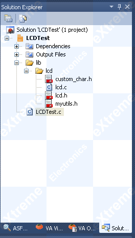
The solution explorer helps us keep the project source files in an organized hierarchal way. In our project there is an main application code file that is the high level application program (say a line LCDTest.c). In this case the file is named LCDTest.c, it is placed in the root of project.
The high level application requires services from lower level codes like the Motor Library, ADC Library etc. All these library are kept in their own folders inside the lib folder.
All our library are deployed in two files namely libname.c and libname.h
The c file contains the actual implementation while the h file contains the prototypes.
The Solution Explorer Tasks.
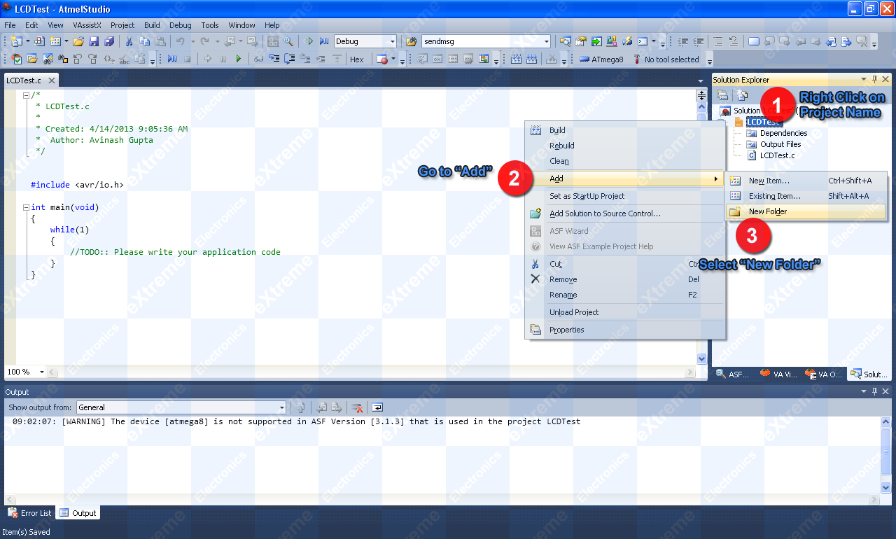
Creating a Folder.
As you have seen above how we organize our project in an Hierarchical way now we will see how to actually do this.
- Right Click on the Project's Name in the solution explorer. This will bring up the project context menu.
- From the context menu select Add->New Folder.
- Name the folder lib.
|
Fig. 8 - Add a new folder. (Click to Enlarge ...) |
in almost all of your projects we will have the lib folder (which stands for library files). The library files have set of functions that makes our life easier. They provide functions to do common tasks. For example LCD Library provide all functions to use the built in LCD Module. It provides functions to clear the LCD, write text and numbers on in it and many other functions too!
eXtreme Electronics provide following library files with xBoard MINI.
- LCD Library: To handle the 16x2 Alpha numeric LCD Module.
- USART Library: to send and receive data by using USART.
- I2C Library: used to interface with I2C devices like RTC,EEPROM, Accelerometer, Temperature Sensor etc.
- ADC Library: functions to initialize the built in ADC of AVR and to get analog readings from it.
- Remote Control Interface Library: It helps you receive data from a standard remote control. This library enable you to create remote controlled devices.
In addition to these low level libraires we also provide some high level libraries that uses these low level libraries to provide high level functions. Following high level libraries are available.
- GSM Library: Uses the USART library to communicate with GSM Module and provide many high level function to control it. You can use this to build devices that can connect with the GSM Network. It enables you to send and receive text messages over GSM Network.
- RTC Library: Uses the I2C library to communicate with an RTC Module. Provides functions to get current time and date.
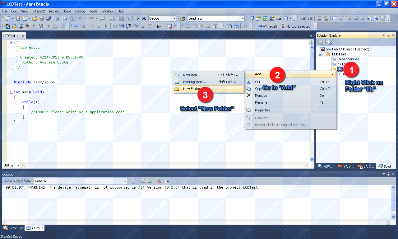
To orgasise our project we create a folder for each library that we going to use in our project. For example if you plan to use the LCD library create a folder named "lcd" inside the "lib" folder.
Steps are as follows.
- Right click on folder named "lib"
- This will open a context menu, from that goto "Add"
- From "Add" submenu select "New Folder"
- Name this new folder as "lcd"
|
Fig. 9 - Add a new subfolder. (Click to Enlarge ...) |
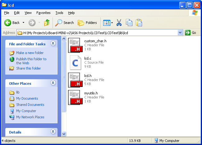
Now when the folders are created in the project, its time to copy some files in the folder. The lcd library consists of following four files.
- lcd.c
- lcd.h
- myutils.h
- custom_char.h
You can download all these files from here.
Extract all these files using utilities like WinZip or WinRAR
You have to copy all these four files to your project's "lib\lcd\" folder using Windows.
- Using "My Computer" go to the place where you have created your AS6 Project.
- In my case it is "H:\My Projects\xBoard-MINI-v2\AS6 Projects\LCDTest"
|
Fig. 10 - Your Project Folder |
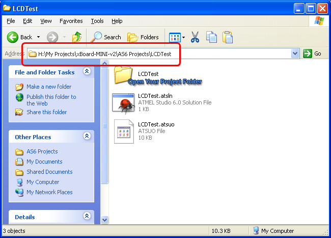
Double click on your project folder (LCDTest in this case), to open it.
Inside that you will see
- A folder named "Debug"
- One or more folders you created using the solution explorer. In this example we have created only one folder named "lib".
- One or more C source files you added to project. In this example we have only one C source file named "LCDTest.c"
- Your main Atmel Studio 6 file which holds all information regarding your project. In this case its name is "LCDTest.cproj"
All this is shown below.
|
Fig. 11 - Locating Your "lib" folder |
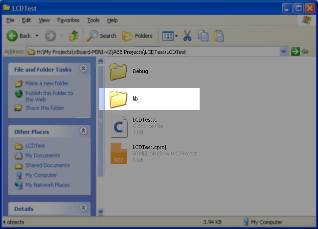
Open the "lib" folder.
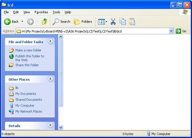
You will see all the sub folder you added to it using the solution explorer.
Since in this example we have created only one sub folder named "lcd" you will only find one folder. Double click to open it.
This folder will be empty.
|
Fig. 12 - Empty folder "lcd" |
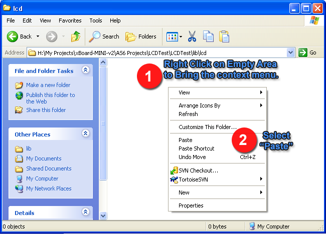
Copy all the four files which makes up the LCD library to this folder.
|
Fig. 13 - Paste lcd library files |
|
Fig. 14 - All four files which makes up the lcd lib |
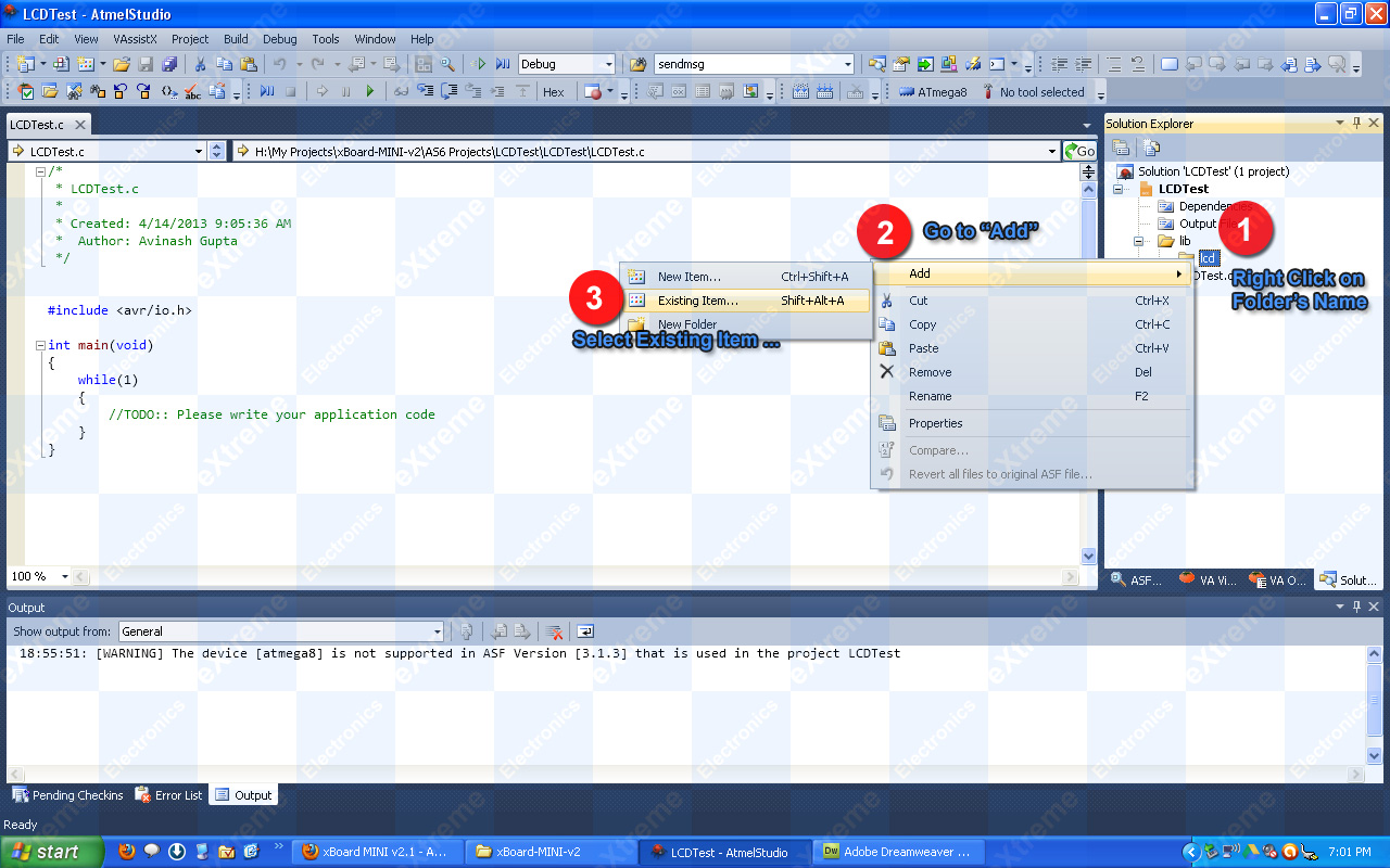
Adding Existing Files to Project.
Once the support files are copied to the project folder (using My Computer) they must be added to the project. To add existing source files to project do the following.
- Right click on the folder in which you want to add the file. For example if you want to add files to lcd sub folder, right click on lcd to bring the context menu.
- Select Add->Existing Item …
|
Fig. 15 - Add Existing Item to AS6. |
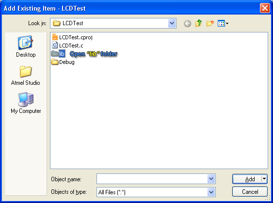
It will open up the add existing item dialog, which will help you select files to add to the project. Open the lib folder. Inside you will see all the subfolders you created using the solution explorer.
|
Fig. 16 - Browse for the files to add. |
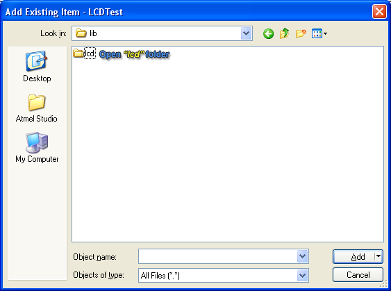
Since we have created only the lcd subfolder inside lib folder, we see only that. Open that folder to view the files for lcd library.
|
Fig. 17 - Open the lcd subfolder. |
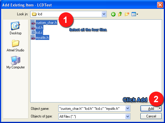
Select all four files which are part of lcd library. And click Add.
|
Fig. 18 - Select all four files. |
|
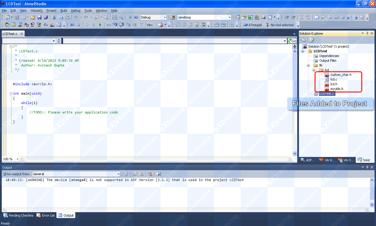
Fig. 19 - Files added to project. |
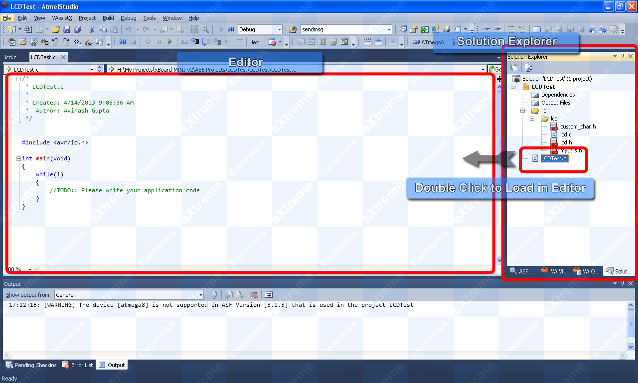
Editing a File In Project
You can double click a file in the solution explorer pane to load it into the main editor.
|
Fig. 20 - Editing a File |
Defining a Preprocessor Symbol
A preprocessor symbol which often used as a global constant can be defined for a project using the project properties dialog.
To bring up the project properties dialog you can do any one of the following.
- Hit Atl+F7 from the keyboard.
- From Project menu select <project name> Properties (last item on Project menu).
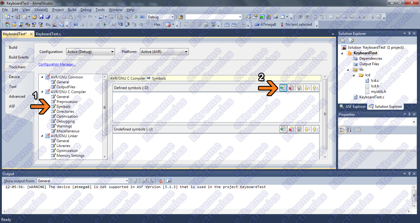
To define a new symbol do the following :-
- From the left hand list on the Project Properties dialog, select Symbols which is under AVR/GNU C Compiler. (Refer Fig. 11)
- Select New Symbol button.
|
Fig. 21 - Project Properties Dialog. |
- In the new dialog that comes, enter <symbol name>=<value> for example F_CPU=16000000 where F_CPU is symbol name and 16000000 is the value.
|
Fig. 22 - Defining a new Symbol. |
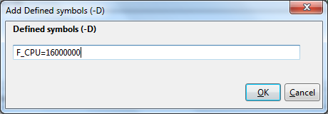
NOTE: One symbol that must be defined in all project is the CPU clock frequency in Hz. This symbol is named F_CPU. Its value must be set according to the speed on which AVR MCU will be running. The xBoard MINI runs at 16MHz so we define F_CPU=16000000 in all your projects.
Building the Project.
Building is the process of compiling(or assembling if file is in assembly language) various source files in the project and linking the output files (.o) to give a final executable hex file.
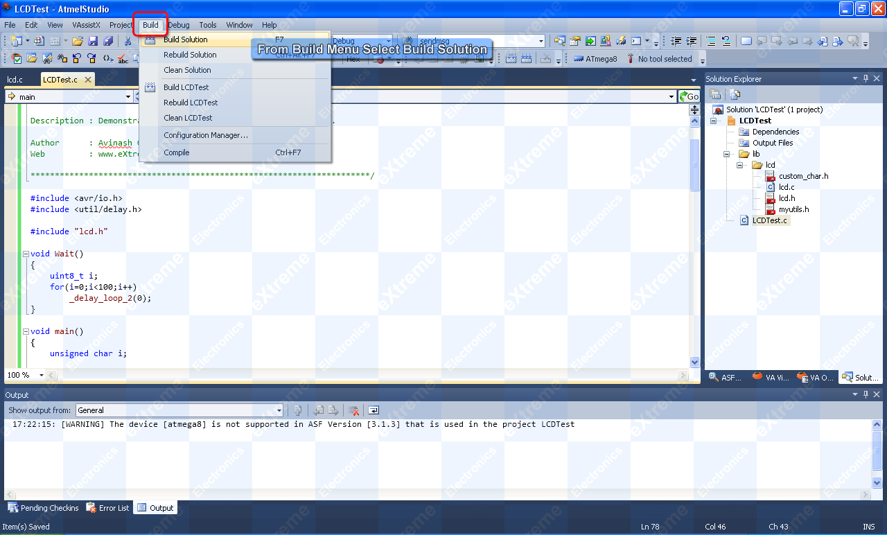
To build the project, select Build Solution from the Build menu. You can also use keyboard shortcut F7 to build the project.
|
Fig. 23 - Building the Solution |
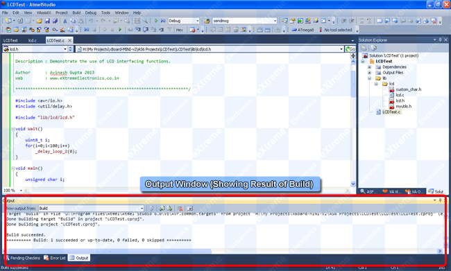
If everything is setup correctly and your source files do not have any syntax error then you will get the following message.
It states the number of projects succeeded and the number of projects failed. Since we have only one project in our solution we should get something like this :-
Build succeeded. ========== Build: 1 succeeded or up-to-date, 0 failed, 0 skipped ==========
|
Fig. 24 - Build Output |
Locating the HEX File
Once the project is build successfully a hex file is generated. You can use any programmer to upload this hex file to your MCU. This hex file is generated inside the folder Debug which is inside the Project folder (LCDTest in our case) which is again inside the solution folder (LCDTest in our case).
How to transfer this hex file to the board is given in this tutorial.
Back |
Support |
Store |
Facebook |